
2 layers44.5 × 46.9 mm
OSO SWAT B1-jig
joeycastillo/Sensor-Watch
A board replacement for the classic Casio F-91W wristwatch
31 parts2.1k

A shield for the Arduino Uno running grbl, to connect to external stepper drivers
Grbl is an open-source printed circuit board by Fablab-Amersfoort, from the Fablab-Amersfoort/grbl-shield repository on GitHub. It is a 2-layer board of 68.5 × 56.6 mm with 31 parts on 44 nets, routed with 132 tracks and 0 vias.
Its parts include 7 connectors, 6 capacitors and 6 resistors. It belongs with the robots and motor control boards and the AVR (ATmega, ATtiny) boards of this library.
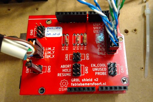
This repository contains the KiCad design files for a grbl shield. It is intended to for an Arduino Uno running grbl, to connect it to external stepper drivers, limit switches and other equipment. The reason for developing this shield, instead of using an existing shield, is that this shield has filtering applied to the limit pins to allow more robust operation in a noisy environment (at Fablab Amersfoort, our limit switches were picking up noise from the parallely running spindle power wires). Other than that, this is a trivial PCB, that just connects pin headers to the Arduino pins.
The repository contains the KiCad design files for the board, under "Releases" in github we also have pre-generated gerber files to use. We have a few spare boards from our own order, which you can order through tindie.
This shield supports both the old (0.8) and new (0.9) Grbl pinout. The
difference is that the limit Z and spindle enable pins are swapped, and
the latter is repurposed to a spindle PWM pin. For the spindle,
switching layouts is a matter of use the right connector (SPIN_EN or
SPIN_PWM), but for the z limit pin, a solder jumper needs to be
soldered in either position (since there is also a filter attached).
The shield connects all three Arduino ground pins to the ground plane. Ideally, you would use only one pin to prevent ground loops, but I wasn't sure which one to use. The one above the digital pins is very close to the limit pin connector and filter, but looking at the Arduino Uno schematic, there is quite some distance and some vias between that pins and the microcontroller. The other two ground pins have a better connection to the microcontroller, but are further away from the limit pins. For now, all of them are connected, if this causes problems, we could try disconnecting some ground pins.
The shield uses SMD components for the filter capacitors, to minimize the distance (and inductance) from the filtered pins and the capacitors. To simplify the layout, the resistors use through-hole versions instead.
In the prototype, 22nF was used, but in the final design these were replaced by 10nF because that was what was available.
A number of components on the limit pins are left empty (NC) in the schematic. Initial testing shows these shouldn't be needed, but if further problems crop up, they could be used to improve the stability of the design by adding smaller pullup resistors (Arduino Uno internal ones are fairly big at 20k-50k), or adding a second filter capacitor of a different size.
The original layout was made for single-sided milling on a CNC mill, so the design does not use any vias. The v1 board was produced like this, v2 was slightly modified for 2-layer commercial production (but it should be easy to make it single-sided again).
This design is made available under the CERN Open Hardware License, version 1.2 or above. See LICENSE.txt for the full text of the license.
| Qty | Value | Footprint | References |
|---|---|---|---|
| 3 | 10n | Capacitor_SMD:C_0805_2012Metric | C1, C3, C5 |
| 3 | 1K | Resistor_THT:R_Axial_DIN0207_L6.3mm_D2.5mm_P7.62mm_Horizontal | R4, R5, R6 |
| 3 | NC | Resistor_THT:R_Axial_DIN0207_L6.3mm_D2.5mm_P7.62mm_Horizontal | R1, R2, R3 |
| 3 | NC | Capacitor_SMD:C_0805_2012Metric | C2, C4, C6 |
| 2 | GND | Connector_PinHeader_2.54mm:PinHeader_2x02_P2.54mm_Vertical | P6, P7 |
| 1 | ARDUINO_UNO | Module:Arduino_UNO_R2_WithMountingHoles | SHIELD1 |
| 1 | CTL | Connector_PinHeader_2.54mm:PinHeader_2x03_P2.54mm_Vertical | P1 |
| 1 | LAYOUT | Jumper:SolderJumper-3_P2.0mm_Open_TrianglePad1.0x1.5mm_NumberLabels | JP1 |
| 1 | LIMIT | Connector_PinHeader_2.54mm:PinHeader_2x03_P2.54mm_Vertical | P5 |
| 1 | MISC | Connector_PinHeader_2.54mm:PinHeader_2x03_P2.54mm_Vertical | P2 |
| 1 | SPIN | Connector_PinHeader_2.54mm:PinHeader_2x03_P2.54mm_Vertical | P4 |
| 1 | STEP | Connector_PinHeader_2.54mm:PinHeader_2x09_P2.54mm_Vertical | P3 |
The 21 most common of 31 parts.
joeycastillo/Sensor-Watch
A board replacement for the classic Casio F-91W wristwatch

hoglet67/RGBtoHDMI
Bare-metal Raspberry Pi project that provides pixel-perfect sampling of Retro Computer RGB/YUV video and conversion to HDMI

hackclub/OnBoard
💡 Join 1,000 teenagers and make your first PCB with a $100 grant!

openwch/ch32v003
CH32V003 is an ultra-cheap RISC-V MCU with 2KB SRAM, 16KB flash, and up to 18 GPIOs that sells for under $0.10

Luos-io/luos_engine
Open-source and real-time orchestrator for cyber-physical-systems, to easily design, test and deploy embedded applications and digital twins.

BlueAndi/Pixelix
Full RGB LED matrix, based on an ESP32 and WS2812B LEDs or emulated LEDs on TFT.


It measures 68.5 × 56.6 mm and has 2 copper layers, 1.6 mm thick.
31 parts. The full list of its parts is on this page, with links to each part's symbol and footprint where PCBKit's library has them.
From the Fablab-Amersfoort/grbl-shield repository on GitHub, at the commit this page was made from: the board is Grbl.kicad_pcb. PCBKit opens the board in the browser, with nothing to install.
Its repository states no licence, so its author keeps all rights: ask Fablab-Amersfoort before reusing the design.