4 layers240 × 180 mm

 FPGA-Research/FABulous_board6
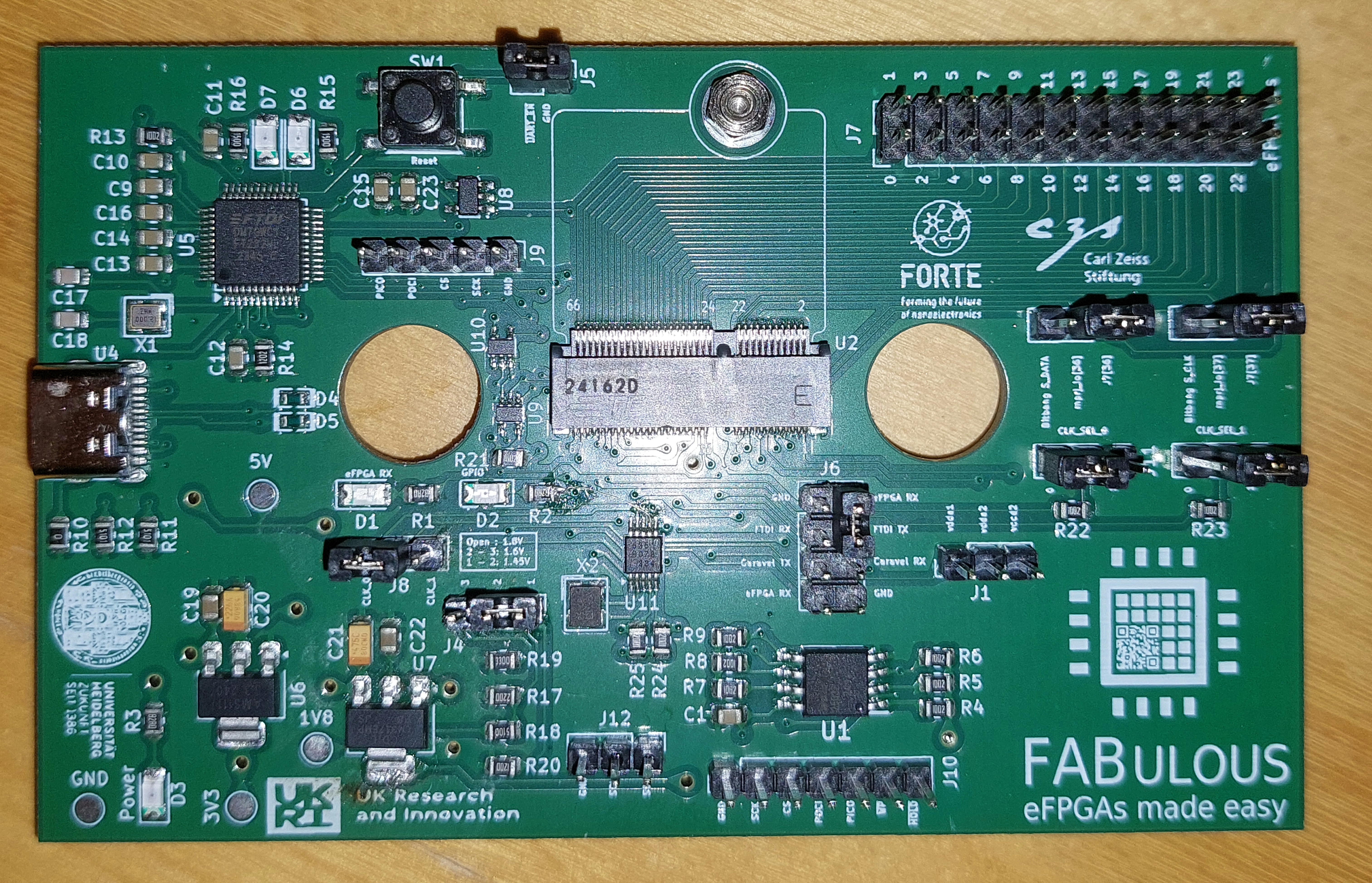
A PCB created for FABulous FPGAs, based on the caravel board.
FABulous board is an open-source printed circuit board by FPGA-Research, from the FPGA-Research/FABulous_board repository on GitHub, published under the Apache-2.0 licence. It is a 4-layer board of 101.2 × 63.5 mm with 85 parts on 115 nets, routed with 878 tracks and 130 vias.
It is built around the SN74LVC1G125DCKR-GK, W25Q32JVSSIQ and AMS1117-3.3V, with the 2199230-4, FT232H and GT-USB-7010ASV among its other parts. Its parts include 25 resistors, 17 capacitors, 13 connectors, 10 ICs and 7 diodes. It belongs with the fPGA and programmable logic boards and the FPGA and CPLD boards of this library.


The PCB created here is used for eFPGAs created using FABulous. It is based on the hardware files of the caravel board repository at Commit 1f99718 and was customized to better fit the exact eFPGA pin configuration.
hardware : Files related to the hardware, like schematics,
board layout and also simulation files.software : Files related to the software needed for eFPGA operation, like
uploading the bitstream.doc: Files related to the project documentation.Compatible to all eFPGAs using the caravel harness.
Three adjustable voltage levels for the core voltage :
→ some boards have just a fixed voltage of 1.5V since a fixed instead of an adjustable LDO was used when the boards were manufactured.
Up to 24 IO pins usable for the eFPGA:
→ depending on how many pins can be successfully configured for each chip and how the bitstream will be uploaded.
Independently configurable clock speeds for SoC and eFPGA.
There are two types of clock selections on the board. One is the selection
between an external clock, the internal wishbone clock, and a so-called user
clock. The external clock is connected to another jumper that will be explained
later. The wishbone clock is the same clock that is also used by the Caravel
SoC. The user clock effectively is the same clock as the wishbone clock.
These clocks can be selected by setting CLK_SEL_0 and CLK_SEL_1 in the
following way:
| CLK_SEL_0 | CLK_SEL_1 | Clock Source |
|---|---|---|
| 0 | X | external (J8) |
| 1 | 0 | wishbone |
| 1 | 1 | user |
The other clock selection is the jumper J8, where two different clocks can be
selected. The clocks depend on the configuration of the SI5351A-B-GTR clock chip
and is only in effect if the external clock is used as the clock source shown in
the above table.
The first fabricated version of the board (v0.1) has the following issues:
S_DATA and S_CLK are interchanged| Qty | Value | Footprint | References |
|---|---|---|---|
| 10 | 0.1uF | Capacitor_SMD:C_0805_2012Metric | C1, C9, C10, C11, C12, C13, C14, C15, C16, C23 |
| 10 | 10k | Resistor_SMD:R_0805_2012Metric | R4, R5, R6, R7, R8, R9, R13, R21, R22, R23 |
| 8 | Conn_01x03_Pin | Connector_PinHeader_2.54mm:PinHeader_1x03_P2.54mm_Vertical | J1, J2, J3, J4, J8, J11, J12, J13 |
| 4 | TestPoint | TestPoint:TestPoint_Pad_D2.0mm | TP1, TP2, TP3, TP4 |
| 3 | 82 | Resistor_SMD:R_0805_2012Metric | R1, R2, R3 |
| 3 | C965826 | LED_SMD:LED_1206_3216Metric | D3, D6, D7 |
| 2 | 10pF | Capacitor_SMD:C_0805_2012Metric | C17, C18 |
| 2 | 10uF | Capacitor_SMD:C_0805_2012Metric | C19, C22 |
| 2 | 150 | Resistor_SMD:R_0805_2012Metric | R15, R16 |
| 2 | 2k | Resistor_SMD:R_0805_2012Metric | R24, R25 |
| 2 | 5.1k | Resistor_SMD:R_0805_2012Metric | R11, R12 |
| 2 | SN74LVC1G125DCKR | Package_TO_SOT_SMD:Texas_R-PDSO-G5_DCK-5 | U9, U10 |
| 1 | 0 | Resistor_SMD:R_0805_2012Metric | R10 |
| 1 | 10u | Capacitor_SMD:C_0805_2012Metric | C24 |
| 1 | 120 | Resistor_SMD:R_0805_2012Metric | R20 |
| 1 | 12K | Resistor_SMD:R_0805_2012Metric | R14 |
| 1 | 220 | Resistor_SMD:R_0805_2012Metric | R17 |
| 1 | 22uF | Capacitor_Tantalum_SMD:CP_EIA-3216-10_Kemet-I | C20 |
| 1 | 330 | Resistor_SMD:R_0805_2012Metric | R19 |
| 1 | 4.7uF | Capacitor_Tantalum_SMD:CP_EIA-3216-10_Kemet-I | C21 |
| 1 | 510 | Resistor_SMD:R_0805_2012Metric | R18 |
| 1 | AMS1117-3_3 | Package_TO_SOT_SMD:SOT-223-3_TabPin2 | U6 |
| 1 | C2977809 | MicroMod-Sparkfun:M.2-CONNECTOR-E | U2 |
| 1 | C434440 | LED_SMD:LED_1206_3216Metric | D1 |
| 1 | C965822 | LED_SMD:LED_1206_3216Metric | D2 |
| 1 | Conn_01x02_Pin | Connector_PinHeader_2.54mm:PinHeader_1x02_P2.54mm_Vertical | J5 |
| 1 | Conn_01x05_Pin | Connector_PinHeader_2.54mm:PinHeader_1x05_P2.54mm_Vertical | J9 |
| 1 | Conn_01x07_Pin | Connector_PinHeader_2.54mm:PinHeader_1x07_P2.54mm_Vertical | J10 |
| 1 | Conn_02x04_Odd_Even | Connector_PinHeader_2.54mm:PinHeader_2x04_P2.54mm_Vertical | J6 |
| 1 | Conn_02x12_Odd_Even | Connector_PinHeader_2.54mm:PinHeader_2x12_P2.54mm_Vertical | J7 |
| 1 | FT232H | Package_QFP:LQFP-48-1EP_7x7mm_P0.5mm_EP3.6x3.6mm | U5 |
| 1 | GT-USB-7010ASV | Customized:USB_C_Receptacle_GCT_USB4105-xx-A_16P_TopMnt_Horizontal | U4 |
| 1 | LOGO | Logos:carl_zeiss_stiftung | T2 |
| 1 | LOGO | Logos:FORTE_logo_square | T3 |
| 1 | LOGO | Logos:heidelberg-university-logo | T4 |
| 1 | LOGO | Logos:ukripluslogo | T5 |
| 1 | LOGO | Logos:fabulous_logo_qr_code_generated_25mm | T1 |
| 1 | M.2 Standoff | MicroMod-Sparkfun:MicroMod-Standoff | H1 |
| 1 | MCP1319MT-29LE-OT | Package_TO_SOT_SMD:SOT-23-5 | U8 |
| 1 | NX3225GA-25_000M-STD-CRG-2 | Crystal:Crystal_SMD_3225-4Pin_3.2x2.5mm | X2 |
| 1 | PGB1010603NR | Capacitor_SMD:C_0603_1608Metric | D5 |
| 1 | PGB1010603NR | Diode_SMD:D_0603_1608Metric | D4 |
| 1 | SI5351A-B-GTR | Package_SO:MSOP-10_3x3mm_P0.5mm | U11 |
| 1 | SPX1117M3-L_TR | Package_TO_SOT_SMD:SOT-223-3_TabPin2 | U7 |
| 1 | TXM12M0004252DBCEO00T | Crystal:Crystal_SMD_2520-4Pin_2.5x2.0mm | X1 |
| 1 | Tactile Switch | Button_Switch_SMD:SW_SPST_Omron_B3FS-101xP | SW1 |
| 1 | W25Q32JVSSIQ | Package_SO:SOIC-8_5.23x5.23mm_P1.27mm | U1 |

njKessel/ESP32s3-NetworkClock
ESP32-S3 smart clock with LED display, weather, moon phase, temperature, Google Calendar

openconcepts-ar/accel2d
This project aims to provide a graphics server system based on hardware accelerated graphics, and a easy way to develop the graphics primitives.

efabless/caravel_board
This repo provides firmware examples, flash programming and diagnostic tools for testing Open MPW and chipIgnite projects using Caravel.


chipfoundry/caravel_board
This repository provides firmware examples, flash programming tools, and diagnostic utilities for testing chipIgnite projects using the Caravel SoC.


MifralTech/Lacerta_CF
An open-source hardware platform that accelerates the design and deployment of customizable graphical interfaces for embedded systems.
It measures 101.2 × 63.5 mm and has 4 copper layers, 1.6 mm thick.
85 parts, built around the SN74LVC1G125DCKR-GK, W25Q32JVSSIQ, AMS1117-3.3V and 2199230-4. The full list of its parts is on this page, with links to each part's symbol and footprint where PCBKit's library has them.
From the FPGA-Research/FABulous_board repository on GitHub, at the commit this page was made from: the board is hardware/kicad_files/project/FABulous_board.kicad_pcb and its schematic hardware/kicad_files/project/FABulous_board.kicad_sch. PCBKit opens the board in the browser, with nothing to install.
Its repository publishes it under the Apache-2.0 licence: you may reuse it on that licence's terms (keep the author's notice, and for a copyleft licence share your changes alike).