2 layers
Mini MCU LINK Integrated
ErichStyger/McuLink-Mini
Version of the NXP MCU-Link Debug CMSIS-DAP Debug Probe.
57 parts32MIT

 ErichStyger/McuLink-Mini32
Version of the NXP MCU-Link Debug CMSIS-DAP Debug Probe.
MCU Link Standalone is an open-source printed circuit board by ErichStyger, from the ErichStyger/McuLink-Mini repository on GitHub, published under the MIT licence. It is a 2-layer board of 46 × 19 mm with 69 parts on 73 nets, routed with 909 tracks and 183 vias.
It is built around the LPC55S69JBD64, XC6227C331PR-G and MI0603J601R-10, with the PMDXB290UNEZ, PESD5V0L5UV and BM03B-SRSS-TB among its other parts. Its parts include 26 capacitors, 11 resistors, 5 diodes, 5 inductors and 3 ICs. It belongs with the NXP (LPC, Kinetis, i.MX RT) boards of this library.


This repository hosts different versions of the original NXP MCU-Link CMSIS-DAP debug probe as open source KiCAD versions. Both as standalone probe or integrated into your design.
Many thanks to Dario Scheuber and his work to make this project possible!
This is the work of Dario Scheuber who created this debug probe as student at the Lucerne University of Applied Sciences and Arts at IET. The project was done under the guidance of Prof. Erich Styger.
See blog article on https://mcuoneclipse.com/2024/02/06/versatile-oshw-mini-mcu-link-debug-probe-external-on-board-or-embedded/ for additional details.
This is an open hardware version of the NXP MCU-Link CMSIS-DAP debug probe, with following features and differences to the original MCU-Link:
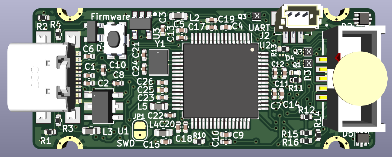
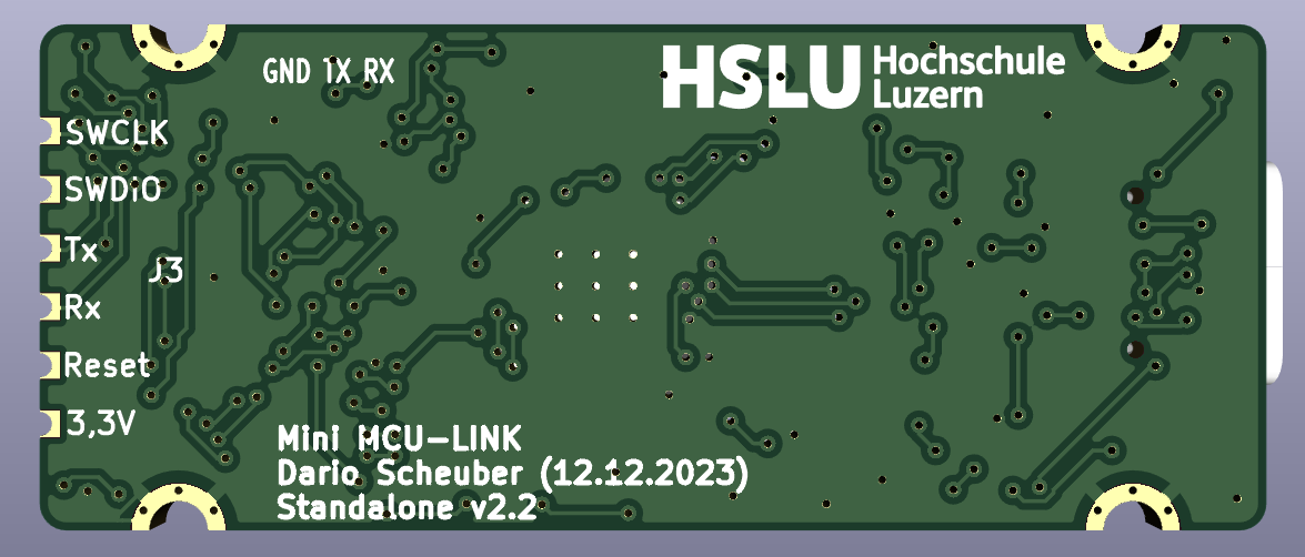
| Qty | Value | Footprint | References |
|---|---|---|---|
| 10 | 100n | Capacitor_SMD:C_0402_1005Metric | C2, C4, C5, C7, C8, C9, C11, C17, C18, C25 |
| 5 | 10n | Capacitor_SMD:C_0402_1005Metric | C6, C12, C13, C14, C16 |
| 4 | MountingHole_Pad | mculink:MountingHole_2.2mm_M2_ISO7380_Pad_TopBottom_with_holes | H1, H2, H3, H4 |
| 3 | 22u | Capacitor_SMD:C_0402_1005Metric | C15, C22, C26 |
| 3 | 47p | Capacitor_SMD:C_0402_1005Metric | C19, C20, C23 |
| 3 | MI0603J601R-10 | Inductor_SMD:L_0603_1608Metric | L2, L3, L4 |
| 3 | PMDXB290UNE | mculink:SOT1216 | Q1, Q2, Q3 |
| 2 | 100k | Resistor_SMD:R_0402_1005Metric | R8, R9 |
| 2 | 10k | Resistor_SMD:R_0402_1005Metric | R3, R5 |
| 2 | 10u | Capacitor_SMD:C_0402_1005Metric | C1, C10 |
| 2 | 2k | Resistor_SMD:R_0402_1005Metric | R6, R10 |
| 2 | 5k1 | Resistor_SMD:R_0402_1005Metric | R1, R2 |
| 2 | 8p | Capacitor_SMD:C_0402_1005Metric | C21, C24 |
| 2 | PESD5V0L5UV | Package_TO_SOT_SMD:SOT-666 | D2, D5 |
| 1 | 10 | Resistor_SMD:R_0402_1005Metric | R11 |
| 1 | 100 | Resistor_SMD:R_0402_1005Metric | R7 |
| 1 | 16.000MHz | mculink:CX3225GA16000D0PTVCC | Y1 |
| 1 | 20k | Resistor_SMD:R_0402_1005Metric | R4 |
| 1 | 3.3V | mculink:castellated pin | H9 |
| 1 | 4u7 | Inductor_SMD:L_0603_1608Metric | L5 |
| 1 | 4u7 | Capacitor_SMD:C_0402_1005Metric | C3 |
| 1 | BM03B-SRSS-TB | mculink:JST_BM03B-SRSS-TB_LF__SN_ | J2 |
| 1 | Conn_02x05_Odd_Even | mculink:SWD_Pin_Header_Straight_2x05_Pitch1.27mm_SMD | J3 |
| 1 | KMR221GLFS | mculink:SW_C_K_KMR2 | SW1 |
| 1 | LED_RED | LED_SMD:LED_0402_1005Metric | D3 |
| 1 | LPC55S69JBD64 | mculink:LQFP-64-1EP_10x10mm_P0.5mm_EP5x5mm | U2 |
| 1 | Logo HSLU | mculink:Hochschule_Luzern_New | L1 |
| 1 | PMEG3005AESFYL | Diode_SMD:Nexperia_DSN0603-2_0.6x0.3mm_P0.4mm | D4 |
| 1 | PRTR5V0U2X | mculink:SOT143B | D1 |
| 1 | RXD | mculink:castellated pin | H5 |
| 1 | Reset | mculink:castellated pin | H10 |
| 1 | STMPS2141STR | mculink:SOT95P280X145-5N | U3 |
| 1 | SWCLK | mculink:castellated pin | H6 |
| 1 | SWD disable | Jumper:SolderJumper-2_P1.3mm_Open_RoundedPad1.0x1.5mm | JP1 |
| 1 | SWDIO | mculink:castellated pin | H8 |
| 1 | TXD | mculink:castellated pin | H7 |
| 1 | USB4110-GF-A_REVB | mculink:USB_C_Receptacle_GCT_USB4110-GF-A | J1 |
| 1 | XC6227C331PR-G | mculink:SOT-89-5 | U1 |
ErichStyger/McuLink-Mini
Version of the NXP MCU-Link Debug CMSIS-DAP Debug Probe.

ErichStyger/MCU-Link-MR
Open Source MCU-Link CMSIS-DAP Debug probe for mobile robots (e.g. Pixhawk)


misko/prompt2device
The separate vNext PCB skill and orchestrator package is available alongside the reference workflow below; existing projects keep their accepted toolchain until an explicit migration.


azonenberg/latentred
Open hardware 48x 1000baseT + 2x 25G SFP28 Ethernet switch

azonenberg/reworkctf
This is a points-based challenge board intended for practicing of PCB rework and circuit editing skills. This is not a circuit debug challenge.
It measures 46 × 19 mm and has 2 copper layers, 1.6 mm thick.
69 parts, built around the LPC55S69JBD64, XC6227C331PR-G, MI0603J601R-10 and PMDXB290UNEZ. The full list of its parts is on this page, with links to each part's symbol and footprint where PCBKit's library has them.
From the ErichStyger/McuLink-Mini repository on GitHub, at the commit this page was made from: the board is hardware/KiCad/mini-MCU-LINK-Standalone/MCU-Link-Standalone.kicad_pcb and its schematic hardware/KiCad/mini-MCU-LINK-Integrated/mini MCU-LINK Debug and UART interface.kicad_sch. PCBKit opens the board in the browser, with nothing to install.
Its repository publishes it under the MIT licence: you may reuse it on that licence's terms (keep the author's notice, and for a copyleft licence share your changes alike).