
2 layers50 × 23.2 mm
Analog
hoglet67/RGBtoHDMI
Bare-metal Raspberry Pi project that provides pixel-perfect sampling of Retro Computer RGB/YUV video and conversion to HDMI
32 parts1kGPL-3.0
 ETAChalmers/CAN-Distributor
CAN Distributor, to simplify connecting things to the CAN bus.
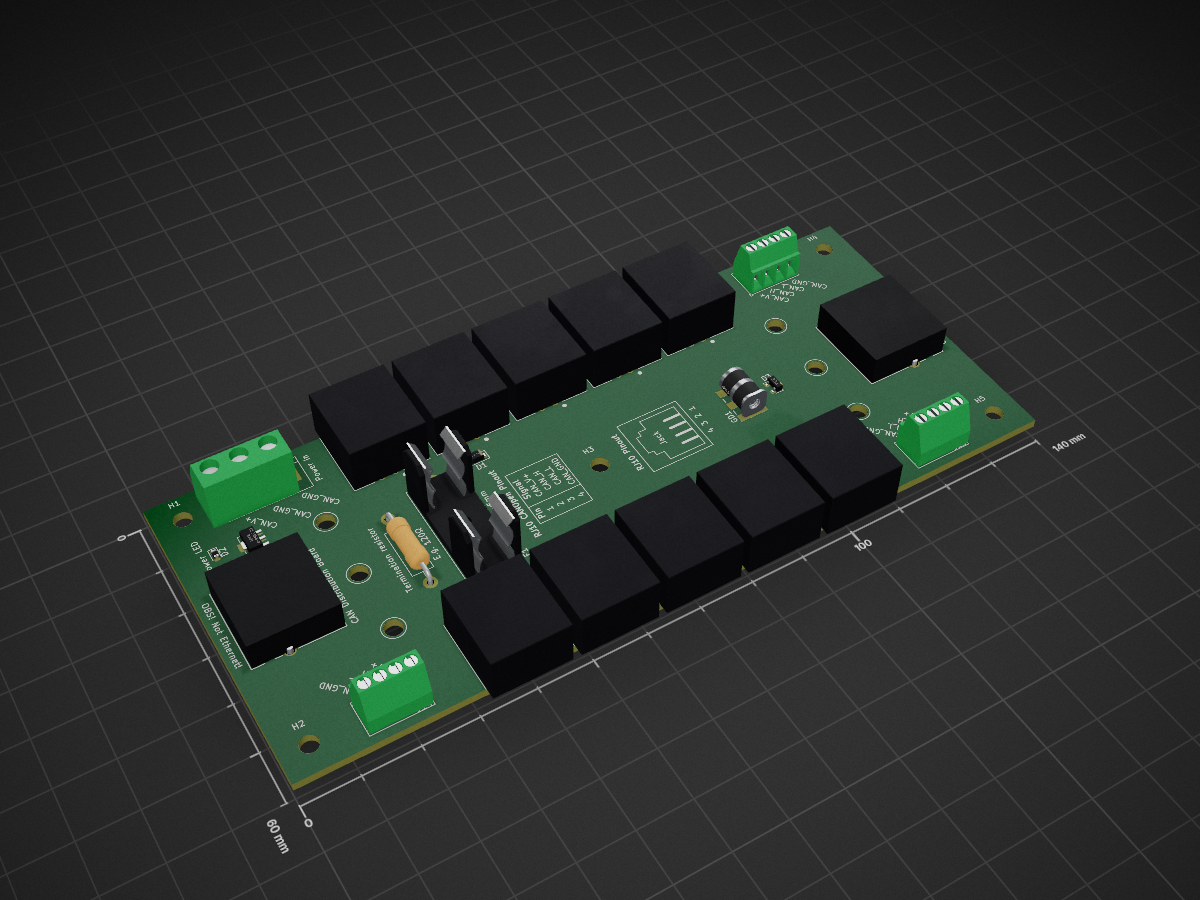
CAN Distributor is an open-source printed circuit board by ETAChalmers, from the ETAChalmers/CAN-Distributor repository on GitHub. It is a 2-layer board of 140 × 60 mm with 32 parts on 14 nets, routed with 375 tracks and 26 vias.
It is built around the CL25N8-G. Its parts include 16 connectors, 3 diodes, 1 resistor, 1 IC and 1 fuse. It belongs with the interfaces and adapters boards of this library.
CAN Distributor, to simplify connecting things to the CAN bus.
Equivalent with RJ22. Pinout is based on the CANOpen standard, as specified in:
https://www.phoenixcontact.com/assets/downloads_ed/global/web_dwl_technical_info/CANopen.pdf

Pinout is based on the CANOpen standard, as specified in:
https://www.phoenixcontact.com/assets/downloads_ed/global/web_dwl_technical_info/CANopen.pdf

Each distribution card delivers CAN and optionally power to its Nodes. Power is only distributed over the Node ports. This is to avoid any complex problems regarding PSU load sharing, ground loops, etc... Power is indicated by PWR_LED. Voltage and allowable current draw depends on the connected PSU.
It is not reasonable to draw more than 200/300 mA over the RJ10 cables.
The board has a footprint for a termination resistor, which may be populated. The resistor should only be populated if the board is at one of the two edges of the CAN network.
The Main ports and Node ports use different connectors to avoid plugging them wrong. The RJ10 ports may either be populated with TE Connectivity's vertical 5520257-2 connectors or horizontal 1-1705949-1 connectors.

All mounting holes are for M3.
The board can be mounted to a DIN rail using Phoenix Contact's 1201578 or 1200993 rail adapters. In that case the board is screwed to the adapters using self tapping M3 plastic screws.

| Qty | Value | Footprint | References |
|---|---|---|---|
| 10 | RJ10 | CAN-Distributor:TE_5520257-2 | J4, J5, J6, J7, J8, J9, J10, J11, J12, J16 |
| 5 | MountingHole_3.2mm_M3_DIN965 | MountingHole:MountingHole_3.2mm_M3_DIN965 | H1, H2, H3, H4, H5 |
| 3 | 4p Terminal Block | TerminalBlock_TE-Connectivity:TerminalBlock_TE_282834-4_1x04_P2.54mm_Horizontal | J13, J14, J15 |
| 2 | DINRailAdapter_3xM3_PhoenixContact_1201578 | MountingEquipment:DINRailAdapter_3xM3_PhoenixContact_1201578 | M1, M2 |
| 2 | RJ45_Shielded | CAN-Distributor:RJHSE5480 | J2, J3 |
| 1 | 120 | Resistor_THT:R_Axial_DIN0411_L9.9mm_D3.6mm_P15.24mm_Horizontal | R1 |
| 1 | 2.5A | Fuse:Fuseholder_Cylinder-5x20mm_Schurter_0031_8201_Horizontal_Open | F1 |
| 1 | 3p Terminal Block | TerminalBlock:TerminalBlock_bornier-3_P5.08mm | J1 |
| 1 | CL25N8-G | Package_TO_SOT_SMD:SOT-89-3 | U1 |
| 1 | D_Schottky | Diode_SMD:D_SOD-123F | D1 |
| 1 | GDT | CAN-Distributor:Bourns_Inc.-2036-07-SM-RPLF-MFG | GD1 |
| 1 | PWR_LED | Diode_SMD:D_0603_1608Metric | D2 |
| 1 | RJ10_CAN_Open_Pinout_Table_Silkscreen | CAN-Distributor:RJ10_CAN_Open_Pinout_Table_Silkscreen | G1 |
| 1 | RJ10_Pinout_Silkscreen | CAN-Distributor:RJ10_Pinout_Silkscreen | G2 |
| 1 | TVS | Package_TO_SOT_SMD:SOT-23 | D3 |
hoglet67/RGBtoHDMI
Bare-metal Raspberry Pi project that provides pixel-perfect sampling of Retro Computer RGB/YUV video and conversion to HDMI

hackclub/OnBoard
💡 Join 1,000 teenagers and make your first PCB with a $100 grant!


octosavvi/ESPKey
Wiegand data logger, replay device and micro door-controller

zmaker/arduino_cookbook
gli sketch del nuovo progetto Arduino Cookbook e dei video di YouTube

murexrobotics/electrical
Highly integrated electronics design and printed circuit boards (PCBs) for the MATE ROV Competition. Attempt the impossible.

swharden/AVR-projects
A collection of standalone AVR projects written in C

hardenedlinux/cheap-pcb
Cheap PCB: Better understanding the current status of hardware supply chain
It measures 140 × 60 mm and has 2 copper layers, 1.6 mm thick.
32 parts, built around the CL25N8-G. The full list of its parts is on this page, with links to each part's symbol and footprint where PCBKit's library has them.
From the ETAChalmers/CAN-Distributor repository on GitHub, at the commit this page was made from: the board is CAN-Distributor.kicad_pcb. PCBKit opens the board in the browser, with nothing to install.
Its repository states no licence, so its author keeps all rights: ask ETAChalmers before reusing the design.