2 layers44.5 × 72.7 mm
OSO SWAT C1-jig
joeycastillo/Sensor-Watch
A board replacement for the classic Casio F-91W wristwatch
28 parts2.1k

 Duckle29/ATX-Power-breakout1
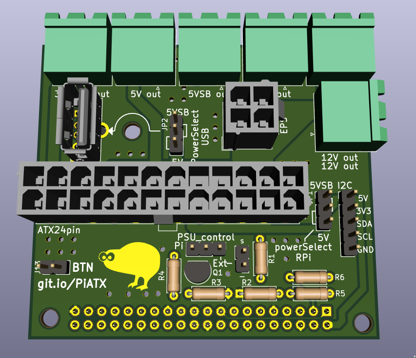
This is a breakout board for an ATX PSU. It's meant to plug onto an RPi and offer PSU control either via the pi or an external controller.
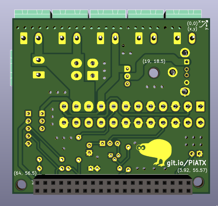
ATX breakout is an open-source printed circuit board by Duckle29, from the Duckle29/ATX-Power-breakout repository on GitHub, published under the MIT licence. It is a 2-layer board of 67 × 59.5 mm with 28 parts on 43 nets, routed with 225 tracks and 54 vias.
Its parts include 13 connectors, 6 resistors and 1 transistor. It belongs with the interfaces and adapters boards of this library.
This is just a simple board that breaks out the different rails of an ATX 24pin connector. It's mainly intented to be used for powering a Raspberry Pi and a 3D printer.
The board includes an EPS 4pin connector as well, allowing for up to 32A on the 12v rail. If you slightly overrun the rated 8A per cable, the 3 12v connectors will handle up to 36A (12A each). This is a 12.5% overload at 9A per cable. Most good cables/connectors should handle that.
The other rails can output 12A max, if the PSU can supply that on that rail.
The board also has a header for selecting how to control the PS_ON signal. It can either be controlled via a transistor controled by the RPi. Aditionally, the "Power Good" signal is also connected to the pi (through a voltage dividier). Lastly, the I2C interface of the Pi is exposed on a 5 pin header, along with 5V 3V3 and Ground.
The 5V supply for the I2C connector and the Pi is selected through the the jumper JP1, while the 5V supply for the USB connector is selected via JP2. You can select between the 5V rail, or the 5V standby rail.
| Pin | Function |
|---|---|
| BCM17 | Power Good |
| BCM9 | Power On |
| BCM26 | BTN to GND |
| Qty | Value | Footprint | References |
|---|---|---|---|
| 4 | 10k | Resistor_THT:R_Axial_DIN0207_L6.3mm_D2.5mm_P7.62mm_Horizontal | R2, R3, R5, R6 |
| 3 | 12V out | Connector_Phoenix_MSTB:PhoenixContact_MSTBA_2,5_2-G_1x02_P5.00mm_Horizontal | J6, J11, J12 |
| 2 | LOGO | graphics:kiwi | G***, G*** |
| 2 | powerSelect | Connector_PinHeader_2.54mm:PinHeader_1x03_P2.54mm_Vertical | JP1, JP2 |
| 1 | 1050570001 | Connector_USB:USB_A_Molex_105057_Vertical | J3 |
| 1 | 1k | Resistor_THT:R_Axial_DIN0207_L6.3mm_D2.5mm_P7.62mm_Horizontal | R4 |
| 1 | 3V3 out | Connector_Phoenix_MSTB:PhoenixContact_MSTBA_2,5_2-G_1x02_P5.00mm_Horizontal | J10 |
| 1 | 5K6 | Resistor_THT:R_Axial_DIN0207_L6.3mm_D2.5mm_P7.62mm_Horizontal | R1 |
| 1 | 5V out | Connector_Phoenix_MSTB:PhoenixContact_MSTBA_2,5_2-G_1x02_P5.00mm_Horizontal | J8 |
| 1 | 5VSB out | Connector_Phoenix_MSTB:PhoenixContact_MSTBA_2,5_2-G_1x02_P5.00mm_Horizontal | J9 |
| 1 | ATX24pin | Connector_Molex:Molex_Mini-Fit_Jr_5566-24A_2x12_P4.20mm_Vertical | J5 |
| 1 | EPS | Connector_Molex:Molex_Mini-Fit_Jr_5566-04A_2x02_P4.20mm_Vertical | J2 |
| 1 | I2C | Connector_PinHeader_2.54mm:PinHeader_1x05_P2.54mm_Vertical | J1 |
| 1 | PSU_control | Connector_PinHeader_2.54mm:PinHeader_1x03_P2.54mm_Vertical | JP3 |
| 1 | Q_NPN_BCE | Package_TO_SOT_THT:TO-92 | Q1 |
| 1 | Raspberry_Pi_2_3 | Connector_PinSocket_2.54mm:PinSocket_2x20_P2.54mm_Vertical | J4 |
| 1 | btn | Connector_PinHeader_2.54mm:PinHeader_1x02_P2.54mm_Vertical | J13 |
| 1 | pson ext | Connector_PinHeader_2.54mm:PinHeader_1x02_P2.54mm_Vertical | J7 |
The 25 most common of 28 parts.
joeycastillo/Sensor-Watch
A board replacement for the classic Casio F-91W wristwatch

TalismanDesign/PocketMage_PDA
An E-Ink PDA device using the ESP32 S3.

rusefi/rusefi
rusefi - GPL internal combustion engine control unit

hackclub/OnBoard
💡 Join 1,000 teenagers and make your first PCB with a $100 grant!

asterics/esp32_mouse_keyboard
ESP32 implementation for HID over GATT Keyboard and Mouse (Bluetooth Low Energy). Including serial API for external modules (similar to Adafruit EZKey HID)


Luos-io/luos_engine
Open-source and real-time orchestrator for cyber-physical-systems, to easily design, test and deploy embedded applications and digital twins.

Chrismettal/EleLab_v2
Cheap DIY lab system for hobbyists and the tinkering folk
It measures 67 × 59.5 mm and has 2 copper layers, 1.6 mm thick.
28 parts. The full list of its parts is on this page, with links to each part's symbol and footprint where PCBKit's library has them.
From the Duckle29/ATX-Power-breakout repository on GitHub, at the commit this page was made from: the board is ATX-breakout.kicad_pcb. PCBKit opens the board in the browser, with nothing to install.
Its repository publishes it under the MIT licence: you may reuse it on that licence's terms (keep the author's notice, and for a copyleft licence share your changes alike).