
2 layers65 × 35 mm
VFD HMI Module
DriveLink-HM/DriveLink
A Variable Frequency Drive, designed and built for Projekt Mechatronik in SoSe26
21 parts2GPL-3.0
 DriveLink-HM/DriveLink2
A Variable Frequency Drive, designed and built for Projekt Mechatronik in SoSe26
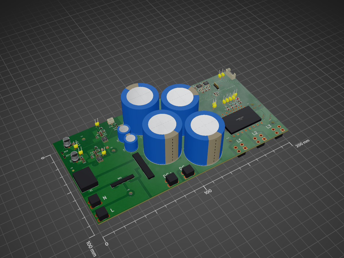
Projekt Mechatronik DC AC is an open-source printed circuit board by DriveLink-HM, from the DriveLink-HM/DriveLink repository on GitHub, published under the GPL-3.0 licence. It is a 4-layer board of 200 × 100 mm with 190 parts on 127 nets, routed with 997 tracks and 166 vias.
It is built around the MP9488GS-P, AP63200WU and AMT0440007DB0000G, with the 1N6857UR-1, 1N914WT and GSF0301 among its other parts. Its parts include 59 capacitors, 46 resistors, 19 diodes, 11 connectors and 9 ICs. It belongs with the STM32 boards of this library.


An open-hardware variable frequency drive (VFD) for three-phase induction motors, developed for the course Projekt Mechatronik at Munich University of Applied Sciences (HM).
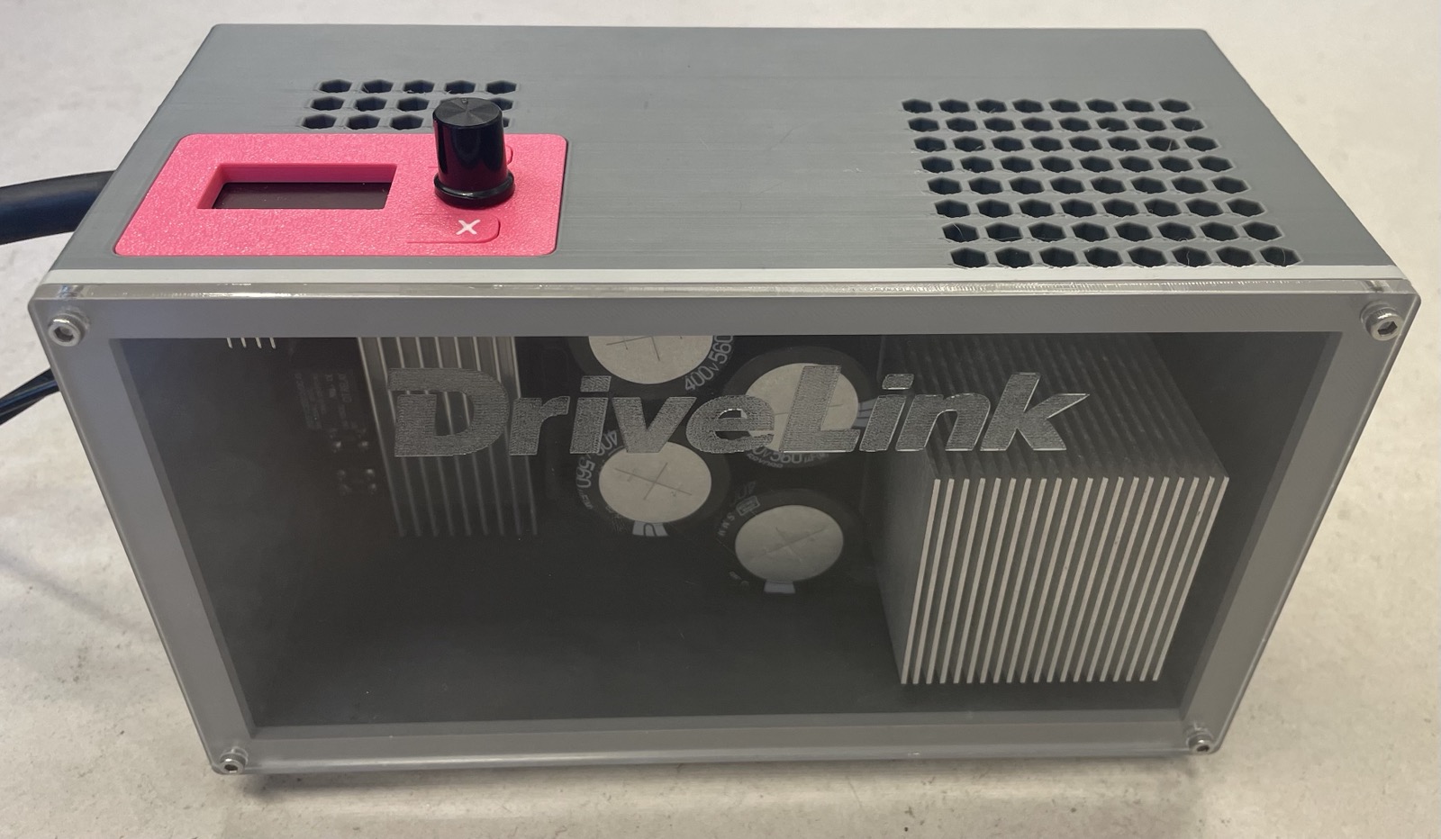
DriveLink rectifies single-phase 230 V AC mains into a ≈325 V DC link and drives the motor through an Infineon IM06B50GC1 CIPOS Mini intelligent power module (600 V / 50 A). The power stage is controlled by an STM32G474 whose firmware is generated from a PLECS model, while a detachable ESP32-S3 HMI provides an OLED display, rotary-encoder control, and a WiFi web dashboard. This repository contains everything needed to reproduce the device: KiCad schematics and PCB layouts, firmware, the PLECS model, enclosure CAD files, and documentation.
⚠️ Safety warning — This device connects directly to mains voltage and its DC link operates at ≈325 V. The DC-link capacitors store a lethal charge even after disconnection. This is a student prototype: it is not certified for mains-connected installations and must only be operated by qualified persons, behind an isolation transformer or RCD, inside a closed enclosure. Reproduce and operate it at your own risk.
Status: working prototype — see Known limitations.
https://github.com/user-attachments/assets/3f33c3a8-9b28-4335-b2a6-baa4afd1d7ac
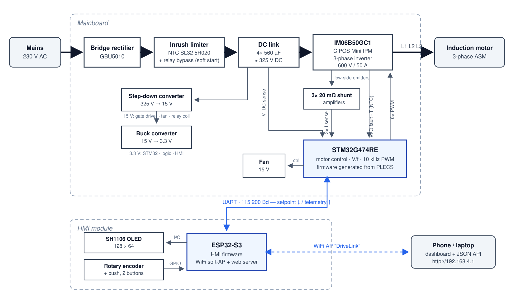
Block schematic of the implemented system (editable source: system-block-diagram.svg).
The system consists of two boards:
rectifier, VFD, STM, Buck_Converter, Step_Down_Converter, cooling).The two boards speak a small framed serial protocol, specified in docs/UART_PROTOCOL.md.
| Path | Content |
|---|---|
| Mainboard/ | KiCad 10 project of the power/controller board, BOM (CSV), STEP model, PCB stand STL |
| HMI/PCB/ | KiCad 10 project of the HMI board |
| HMI/Firmware/ | PlatformIO project for the ESP32-S3 HMI firmware |
| HMI/pc_testing/ | PC-side test utilities for dashboard and UART development |
| plecs/ | PLECS model VFD_SW.plecs (simulation + STM32 code generation) |
| plecs/dirty_patch/ | Build script and reference copies of the UART code embedded in the model |
| case/ | Enclosure: Fusion 360 archive, STEP files, front bezel STL, fan impeller |
| docs/ | Project report (German), block diagram, datasheets, poster, protocol spec |
| Tool | Needed for | Notes |
|---|---|---|
| KiCad 10+ | Viewing/editing PCBs, Gerber export | Project files are in KiCad 10 format and will not open in older versions |
| PLECS 5.0+ with PLECS Coder | Simulation and STM32 code generation | Coder license with the STM32 target family required |
| PlatformIO | Building/flashing the HMI firmware | CLI or VS Code extension |
| Arm GNU Toolchain + GNU Make | Compiling the generated STM32 code | arm-none-eabi-gcc and make must be on PATH |
| PowerShell | Running build.ps1 | Preinstalled on Windows; pwsh works on Linux/macOS |
| STM32CubeProgrammer + ST-LINK | Flashing the STM32 | Any SWD-capable probe works |
| Python 3 (optional) | PC test utilities | pip install pyserial requests |
| Fusion 360 / slicer (optional) | Modifying/printing the enclosure | STEP and STL files are included |
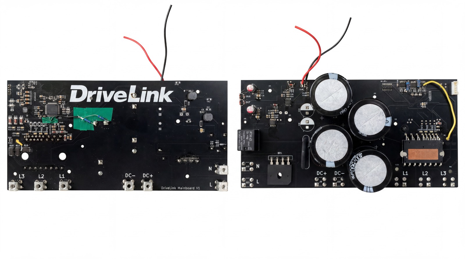 Assembled DriveLink mainboard (front and back).
Open Mainboard/Projekt_Mechatronik_DC-AC.kicad_pro and HMI/PCB/VFD-HMI-Module.kicad_pro in KiCad 10.
Export Gerber and drill files (File → Fabrication Outputs) and order the boards — the prototypes were manufactured by JLCPCB with default settings.
Source the components: the mainboard BOM is included as Projekt_Mechatronik_DC-AC.csv (semicolon-separated, with datasheet links); export the HMI BOM from KiCad if needed. Key parts:
| Function | Part | Manufacturer |
|---|---|---|
| Power module (3-phase inverter) | IM06B50GC1 (600 V / 50 A) | Infineon |
| Motor controller | STM32G474RETx | STMicroelectronics |
| HMI controller | ESP32-S3 module | Espressif |
| Rectifier | GBU5010 | MCC |
| Inrush limiter (NTC) | SL32 5R020 | Ametherm |
| DC-link capacitors | 4× ESMM401VSN561MA40S, 560 µF / 400 V | Chemi-Con |
| Current shunts | 3× GMR100HJBFHR020, 20 mΩ / 7 W | Rohm |
Assemble and solder the boards (mostly SMD; the power module, connectors, and electrolytics are through-hole).
The case/ folder contains the printable enclosure:
housing.f3z / housing.step — the main enclosure (Fusion 360 archive and neutral STEP)HMI_blende.stl — front bezel for display, encoder, and buttonsPropeller_groß.f3d / .step — impeller for the cooling fanPrint the STLs on any FDM printer (no special settings required); use the STEP/F3Z sources to adapt the design.
The device runs two firmwares: the HMI firmware (hand-written, PlatformIO) and the motor-control firmware (generated from the PLECS model).
cd HMI/Firmware
pio run -e esp32-s3-devkitc-1                 # build
pio run -e esp32-s3-devkitc-1 -t upload       # flash via USB
pio device monitor -b 115200                  # serial log
platformio.ini defines two environments: esp32-s3-devkitc-1 for the actual HMI hardware and esp32 for bench tests on a generic ESP32 devkit. All library dependencies (U8g2, ESP32Encoder, ESPAsyncWebServer, ArduinoJson) are fetched automatically on first build.
The PLECS model is the single source of truth for the motor control — the STM32 code is generated, not written by hand:
Open plecs/VFD_SW.plecs in PLECS (the Coder target STM32G4x is preconfigured in the model).
Open Coder → Coder options…, choose an output directory (e.g. plecs/VFD_SW_codegen, which is gitignored), and click Build to generate the sources (VFD_SW_1.c, …) and the makefile VFD_SW.mk.
Copy plecs/dirty_patch/build.ps1 into the output directory and run it:
cd plecs/VFD_SW_codegen
pwsh ./build.ps1     # or run in Windows PowerShell
The script activates the embedded UART code (see below) and runs make clean && make, producing an .elf binary.
Connect an ST-LINK to the mainboard's SWD header and flash the .elf with STM32CubeProgrammer.
The generated firmware needs UART code (STM32 HAL) to talk to the HMI, but PLECS also compiles the model's C-Script for host-side simulation, where no HAL exists. The UART implementation therefore lives inside the model's C-Script blocks wrapped in comment guards:
/*//                      ← guard line: everything below is a comment…
#define UART_ENABLED
... real UART code ...
//*/                      ← …until here

#ifndef UART_ENABLED
void uart_init(void) {}   /* no-op stubs used during simulation */
...
#endifbuild.ps1 deletes the guard lines from the generated VFD_SW_1.c, activating the real implementation before calling make.The files in plecs/dirty_patch/ (code_declarations.c, start_function_code.c, output_function_code.c) are reference copies of those C-Script sections. To change the UART code, edit it inside the PLECS model and keep the copies in sync.
| Control | Action |
|---|---|
| Rotary encoder | Select the frequency setpoint (−100 … +100 Hz; negative values reverse rotation) |
| Encoder push | Apply the selected setpoint to the output |
| Confirm button | Toggle static/dynamic mode — in dynamic mode the output follows the encoder live, without pressing |
| Back button | Enable / disable the output (STOPPED) |
The display shows the live output frequency (large, right) and the pending setpoint (left, in static mode) in the top half, and DC-link voltage plus module temperature in the bottom half. When the output is disabled, STOPPED is shown and 0 Hz is commanded.
The HMI opens its own WiFi access point:
DriveLink — Password: DriveLink123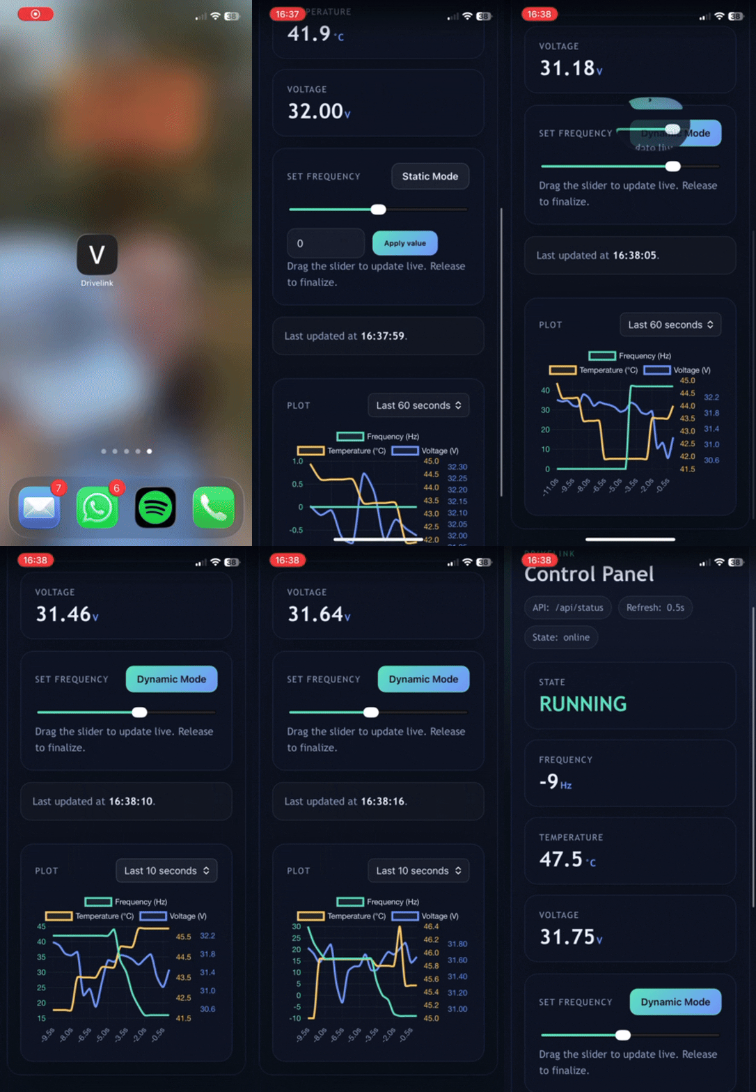
The dashboard is backed by a small JSON API that can also be used directly:
# Read telemetry
curl http://192.168.4.1/api/status
# → {"frequency_hz":50.00,"voltage_v":324.10,"temperature_c":42.5,"output_disabled":false}

# Set the frequency setpoint (clamped to −100…+100 Hz)
curl -X PUT http://192.168.4.1/api/status \
     -H "Content-Type: application/json" \
-d '{"frequency_hz": 42}'HMI/pc_testing/ contains helpers for working on the HMI without a powered mainboard:
web_test.py — serves the dashboard locally at http://127.0.0.1:8000 with simulated telemetry, and can forward setpoints to a connected device; useful for dashboard UI work. The browser assets (static.html, chart.js) are the sources for the copies embedded in HMI/Firmware/include/web.h — after editing them, update the raw literals there.uart_test.py — emulates a mainboard on a USB-UART adapter, answering setpoints with a rough induction-motor model. Note that it still speaks an older protocol revision (see docs/UART_PROTOCOL.md).Honest notes from the project report and code:
Developed as part of Projekt Mechatronik at Munich University of Applied Sciences (HM), supervised by Prof. Dr. Marek Galek and Prof. Dr. Ulrich Unterhinninghofen:
This project is licensed under the GNU General Public License v3.0 — see LICENSE.
| Qty | Value | Footprint | References |
|---|---|---|---|
| 14 | 1nF | Capacitor_SMD:C_0805_2012Metric | C2, C3, C4, C5, C6, C12, C13, C14, C17, C20, C21, C51, C52, C53 |
| 13 | TestPoint_2Pole | TestPoint:TestPoint_2Pads_Pitch2.54mm_Drill0.8mm | TP4, TP5, TP6, TP7, TP9, TP10, TP11, TP12, TP13, TP14, TP15, TP20, TP21 |
| 11 | 100 | Resistor_SMD:R_0805_2012Metric | R6, R7, R8, R9, R10, R11, R20, R21, R22, R45, R48 |
| 10 | 100nF | Capacitor_SMD:C_0805_2012Metric | C1, C9, C11, C19, C29, C64, C65, C66, C67, C68 |
| 8 | 100n | Capacitor_SMD:C_0603_1608Metric | C_bypass_STM2, C16, C42, C43, C44, C45, C46, C48 |
| 7 | 1k | Resistor_SMD:R_0805_2012Metric | R1, R2, R3, R4, R28, R32, R37 |
| 7 | 22µF | Capacitor_SMD:C_1206_3216Metric | C7, C8, C10, C32, C33, C34, C35 |
| 7 | AMT0440007DB0000G | Benutzerdefiniert:AMT0440007DB0000G | J5, J6, J8, J9, J10, J11, J12 |
| 7 | MountingHole | MountingHole:MountingHole_3.2mm_M3 | H4, H5, H6, H7, H8, H9, H10 |
| 6 | 10k | Resistor_SMD:R_0805_2012Metric | R5, R18, R25, R26, R36, R38 |
| 4 | 1mF | Capacitor_THT:CP_Radial_D35.0mm_P10.00mm_SnapIn | C54, C55, C56, C57 |
| 4 | 20V | Diode_SMD:D_MiniMELF | D1, D2, D3, D4 |
| 3 | 1N6857UR | Diode_SMD:D_MELF | D13, D14, D15 |
| 3 | 1µF | Capacitor_SMD:C_0805_2012Metric | C23, C49, C63 |
| 3 | 9.09k | Resistor_SMD:R_0805_2012Metric | R27, R31, R35 |
| 3 | GMR100HJBFHR020 | Benutzerdefiniert:GMR100HJBFHR020 | R13, R14, R15 |
| 3 | MCP6N11-001E_SN | Benutzerdefiniert:SOIC127P600X175-8N | IC2, IC3, IC4 |
| 3 | MountingHole | MountingHole:MountingHole_2.2mm_M2 | H1, H2, H3 |
| 2 | 1.2mH | Inductor_SMD:L_TDK_NLV32_3.2x2.5mm | L1, L2 |
| 2 | 100k | Resistor_SMD:R_0805_2012Metric | R46, R49 |
| 2 | 100nF, @450V | Capacitor_SMD:C_1206_3216Metric | C24, C25 |
| 2 | 100µF, @35V | Capacitor_SMD:CP_Elec_6.3x7.7 | C50, C62 |
| 2 | 10µF | Capacitor_SMD:C_0805_2012Metric | C18, C28 |
| 2 | 10µF, @450V | Capacitor_THT:CP_Radial_D12.5mm_P5.00mm | C36, C58 |
| 2 | 1N4148 | Diode_SMD:D_SOD-323 | D5, D10 |
| 2 | 1N914WT | Diode_SMD:D_SOD-523 | D16, D19 |
| 2 | 1u | Capacitor_SMD:C_0603_1608Metric | C15, C47 |
| 2 | 2.2µF | Capacitor_SMD:C_0805_2012Metric | C37, C60 |
| 2 | 220nF | Capacitor_SMD:C_0805_2012Metric | C39, C61 |
| 2 | 23.7k | Resistor_SMD:R_0805_2012Metric | R16, R39 |
| 2 | 2k | Resistor_SMD:R_0805_2012Metric | R40, R41 |
| 2 | 3k | Resistor_SMD:R_0805_2012Metric | R19, R44 |
| 2 | 4.99k | Resistor_SMD:R_0805_2012Metric | R17, R43 |
| 2 | 470pF | Capacitor_SMD:C_0805_2012Metric | C38, C59 |
| 2 | 6,8p | Capacitor_SMD:C_0603_1608Metric | C40, C41 |
| 2 | AR1FJ-M3_H | Benutzerdefiniert:SODFL3718X108N | D6, D12 |
| 2 | BLM21AG601SN1D | Inductor_SMD:L_0805_2012Metric | L9, L10 |
| 2 | GSF0301 | Package_TO_SOT_SMD:SOT-523 | Q1, Q2 |
| 2 | LED | LED_SMD:LED_0805_2012Metric | D8, D9 |
| 2 | MP9488GS-P | Benutzerdefiniert:SOIC127P600X175-8N | IC1, IC5 |
| 2 | RB588VYM100FHTR | Benutzerdefiniert:TDZVTR51 | D17, D18 |
| 2 | STTH1R06AF | Benutzerdefiniert:SODFL4724X103N | D7, D11 |
| 2 | SolderJumper_3_Open | Jumper:SolderJumper-3_P1.3mm_Open_RoundedPad1.0x1.5mm_NumberLabels | JP1, JP2 |
| 1 | 0 | Resistor_SMD:R_0805_2012Metric | R29 |
| 1 | 100 | Resistor_SMD:R_0603_1608Metric | R42 |
| 1 | 100pF | Capacitor_SMD:C_0805_2012Metric | C30 |
| 1 | 18,2k | Resistor_SMD:R_0603_1608Metric | R23 |
| 1 | 22nF | Capacitor_SMD:C_0504_1310Metric | C22 |
| 1 | 4u7 | Capacitor_SMD:C_0603_1608Metric | C31 |
| 1 | 6,2k | Resistor_SMD:R_0603_1608Metric | R24 |
| 1 | 6.8u | Benutzerdefiniert:NRS5030T6R8MMGJ | L6 |
| 1 | 68 | Resistor_SMD:R_0805_2012Metric | R12 |
| 1 | 80; 0,2W | Resistor_SMD:R_0805_2012Metric | R47 |
| 1 | AP63200WU | Package_TO_SOT_SMD:TSOT-23-6 | U2 |
| 1 | Conn_01x02_MountingPin | Connector_JST:JST_GH_BM02B-GHS-TBT_1x02-1MP_P1.25mm_Vertical | J1 |
| 1 | Conn_01x05_Pin | Connector_JST:JST_PH_B5B-PH-K_1x05_P2.00mm_Vertical | J2 |
| 1 | Conn_01x06_Pin | Connector_PinHeader_1.27mm:PinHeader_1x06_P1.27mm_Vertical | J7 |
| 1 | Conn_ST_STDC14 | Connector_PinHeader_1.27mm:PinHeader_2x07_P1.27mm_Vertical_SMD | J3 |
| 1 | GBU5010-BP | Benutzerdefiniert:GBU6MBPC01 | BR1 |
| 1 | IM06B50GC1 | Benutzerdefiniert:IM564-X6D | U1 |
| 1 | J107F1CS2012VDC.45 | Benutzerdefiniert:J107F1CS2012VDC45 | K1 |
| 1 | NX2016SA24S08891 | Crystal:Crystal_SMD_2016-4Pin_2.0x1.6mm | Y2 |
| 1 | SL325R020 | Benutzerdefiniert:SL325R020 | RT1 |
| 1 | STM32G474RETx | Package_QFP:LQFP-64_10x10mm_P0.5mm | U4 |
| 1 | SolderJumper_2_Open | Jumper:SolderJumper-2_P1.3mm_Open_RoundedPad1.0x1.5mm | JP3 |
| 1 | TLV9041IDBVRG4 | Benutzerdefiniert:SOT95P280X145-5N | IC6 |
| 1 | TestPoint_2Pole | TestPoint:TestPoint_2Pads_Pitch5.08mm_Drill1.3mm | TP19 |
DriveLink-HM/DriveLink
A Variable Frequency Drive, designed and built for Projekt Mechatronik in SoSe26


UCDFS/Circuits
KiCad projects and PCB designs for UCDFS electronic circuits.

deanasmith/vision-arm
should be any of the following: - calibrate: Calibrate the cameras with the charuco board - track: Start tracking with multiple cameras - mono: Start with a single camera (mostly for debugging)

Queens-Rocket-Engineering-Team/gse-control-node
The GSE control node is the control PCB for GSE systems to integrate with launch control. This includes actuator control, fan control, and a load cell reading.


prototipado/ECG_Phantom
Ecosistema abierto para el diseño, simulación, generación de bioseñales electrocardíacas y monitoreo en tiempo real.

It measures 200 × 100 mm and has 4 copper layers, 1.6 mm thick.
190 parts, built around the MP9488GS-P, AP63200WU, AMT0440007DB0000G and 1N6857UR-1. The full list of its parts is on this page, with links to each part's symbol and footprint where PCBKit's library has them.
From the DriveLink-HM/DriveLink repository on GitHub, at the commit this page was made from: the board is Mainboard/Projekt_Mechatronik_DC-AC.kicad_pcb and its schematic HMI/PCB/VFD-HMI-Module.kicad_sch. PCBKit opens the board in the browser, with nothing to install.
Its repository publishes it under the GPL-3.0 licence: you may reuse it on that licence's terms (keep the author's notice, and for a copyleft licence share your changes alike).