2 layers68 × 79 mm
BrainRing Wireless Admin
Mark-RT/BrainRing_Wireless
Разработка для игры BrainRing - беспроводная версия. Участников до 5. Для устройства ведущего есть прошивка master, а для всех участников одна прошивка slave.
41 parts

 Domochip/WDS18B203
Large DS18B20 network and D1Mini under Tasmota
WDS18B20 is an open-source printed circuit board by Domochip, from the Domochip/WDS18B20 repository on GitHub. It is a 2-layer board of 25.4 × 27 mm with 13 parts on 20 nets, routed with 68 tracks and 0 vias.
It is built around the AMS1117-3.3, AO3400A and MMBT2222A. Its parts include 5 resistors, 3 connectors, 2 capacitors, 2 transistors and 1 IC. It belongs with the home automation and IoT boards and the ESP8266 boards of this library.


This project allows you to build a wide DS18B20 sensors network over a house
It uses :
In order to get a wide 1-Wire bus (one that cover a house), Dallas provides some recommendations into their application note AN148.
This project use the Improved Interface bellow that is able to support a 200 meters long bus:
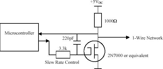
This one requires a pin for reading the bus state and another one as output to drive the bus low : I named it the "Dual Pin OneWire"
Warning : If you build a large 1 Wire bus inside your house, keep in mind that some voltage may appear on this one by induction. You need to have a good knowledge about electricity and associated risks!!!
All files are inside schematic subfolder and has been designed with KiCad
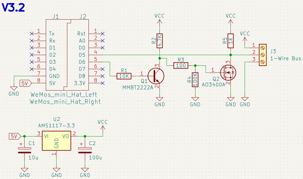
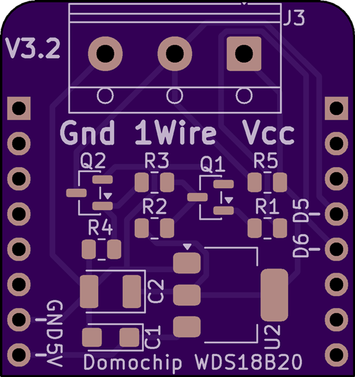
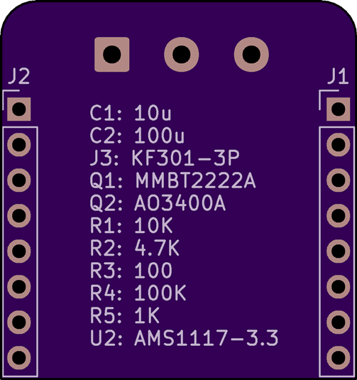
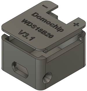
Box project (Fusion 360) and STL files can be found into box folder
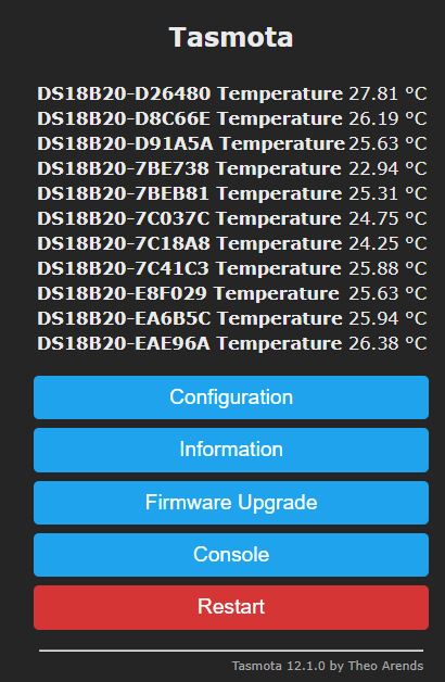
A specific variation in the Tasmota code needs to be done before compilation.
Compile it yourself by following bellow steps OR precompiled binaries are available in Releases.
You need to follow the Tasmota compilation guide to be ready for compilation.
Edit tasmota/tasmota/user_config_override.h file
#define DS18x20_USE_ID_ALIAS to use aliases (Tasmota DS18x20 documentation)#define DS18X20_MAX_SENSORS 16 if you plan to have more than 8 sensors (Tasmota DS18x20 documentation)Compile Tasmota
Rename resulting tasmota.bin to tasmota-WDS18B20-16.0.0.bin
You will find all available tools to flash tasmota in the official documentation:
Tasmota getting started guide
You need to apply this Template:
{"NAME":"WDS18B20","GPIO":[0,0,0,0,0,0,0,0,1344,0,1312,0,0,0],"FLAG":0,"BASE":18,"CMND":"Module 0|TelePeriod 60"}
To change number of digit after the dot on reported temperatures:
TempRes 2
To Enable arithmetic mean over teleperiod:
SetOption126 1
For more details, please refer to the Tasmota DS18x20 documentation.
| Qty | Value | Footprint | References |
|---|---|---|---|
| 1 | 1-Wire Bus | TerminalBlock_RND:TerminalBlock_RND_205-00013_1x03_P5.00mm_Horizontal | J3 |
| 1 | 100 | Resistor_SMD:R_0805_2012Metric | R3 |
| 1 | 100K | Resistor_SMD:R_0805_2012Metric | R4 |
| 1 | 100u | Capacitor_Tantalum_SMD:CP_EIA-3528-21_Kemet-B | C2 |
| 1 | 10K | Resistor_SMD:R_0805_2012Metric | R1 |
| 1 | 10u | Capacitor_Tantalum_SMD:CP_EIA-3216-18_Kemet-A | C1 |
| 1 | 1K | Resistor_SMD:R_0805_2012Metric | R5 |
| 1 | 4.7K | Resistor_SMD:R_0805_2012Metric | R2 |
| 1 | AMS1117-3.3 | Package_TO_SOT_SMD:SOT-223-3_TabPin2 | U2 |
| 1 | AO3400A | Package_TO_SOT_SMD:SOT-23 | Q2 |
| 1 | MMBT2222A | Package_TO_SOT_SMD:SOT-23 | Q1 |
| 1 | WeMos_mini_Hat_Left | wemos_d1_mini:WeMos_D1_mini_Hat_Left | J1 |
| 1 | WeMos_mini_Hat_Right | wemos_d1_mini:WeMos_D1_mini_Hat_Right | J2 |
Mark-RT/BrainRing_Wireless
Разработка для игры BrainRing - беспроводная версия. Участников до 5. Для устройства ведущего есть прошивка master, а для всех участников одна прошивка slave.

retrobuiltRyan/4x4_Rover_ESP32
1:10 scale robot Rover with ESP32 and PS4 controller. Custom PCB for multi channel motor control

rice-eclipse/flight-computer
Custom STM32-Based flight computer to gather data from IMUs, altimeters, and GPS, and control in-flight pyrotechnic events.


retrobuiltRyan/esp32c3_xiao_iot_pcb
PCB for MQTT projects. Sensor, i2c, Screen, and buck converter breakout


lukasprojects/esp32-dalitester
Small ESP32 DALI tester for commissioning and maintaining light installations via the DALI bus

almondsun/DynamicSystemsAndControl
Dynamic Systems and Control coursework: Buck converter modeling, reports, KiCad PCB and STM32 firmware
It measures 25.4 × 27 mm and has 2 copper layers, 1.6 mm thick.
13 parts, built around the AMS1117-3.3, AO3400A and MMBT2222A. The full list of its parts is on this page, with links to each part's symbol and footprint where PCBKit's library has them.
From the Domochip/WDS18B20 repository on GitHub, at the commit this page was made from: the board is schematic/WDS18B20.kicad_pcb and its schematic schematic/WDS18B20.kicad_sch. PCBKit opens the board in the browser, with nothing to install.
Its repository states no licence, so its author keeps all rights: ask Domochip before reusing the design.