2 layers23.2 × 52.1 mm
 Djayden-R/Smart-Doorbell-Kit
A device that makes a standard doorbell smart and connect it to Home Assistant
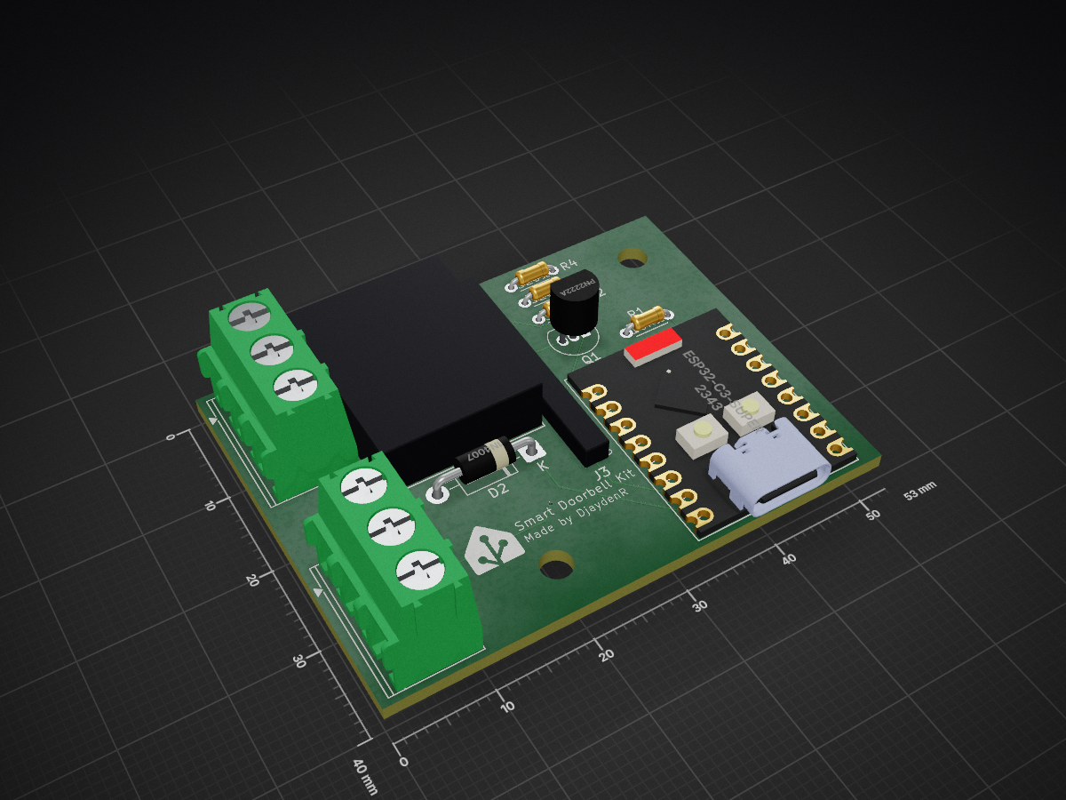
Doorbell mod is an open-source printed circuit board by Djayden-R, from the Djayden-R/Smart-Doorbell-Kit repository on GitHub. It is a 2-layer board of 53 × 40 mm with 12 parts on 29 nets, routed with 51 tracks and 1 via.
It is built around the PN2222A and SRD-05VDC-SL-C. Its parts include 4 resistors, 3 connectors, 1 IC, 1 diode and 1 transistor. It belongs with the home automation and IoT boards and the ESP32 and RISC-V boards of this library.


A device that makes a standard doorbell into a smart doorbell that can connect to Home Assistant.
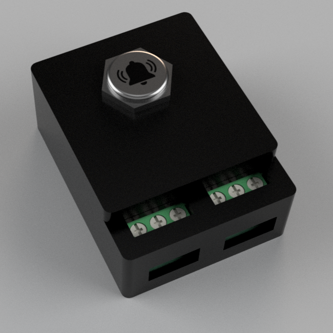
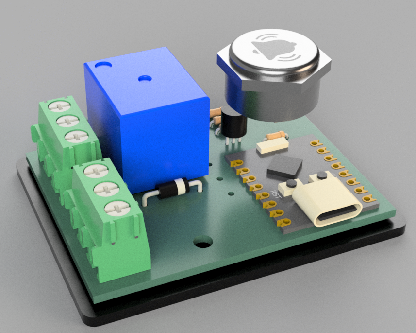

This device has 6 screw terminals, these are for the 8V AC power, the doorbell, and the chime.
After flashing the ESP with the provided firmware it wil be able to connect to Home Assistant using the ESPHome integration. This will then expose a few different sensors:
on/off)timestamp)on/off)switch)In order to toggle mute mode you must press the button on the device twice fast and then it will turn red (mute) or green (unmute).
If you want a custom tune you must edit the then: part of the script:.
I made this device because our doorbell is pretty quiet, which means that if I am in my room I often miss it when the doorbell rings. So whenever I expect the doorbell to ring I need to hold my door open and only have one earbud in so I can actually hear the doorbell. I found this very impractical and so I decided that the solution would be to make my doorbell smart. This way I could just use my smart speaker cranked to the max volume to alert me and even send out notifications to my phone with an attached image from the security camera.
The main part of the electronics is the PCB. Assembling it should be pretty easy, since the components are already labled on the silkscreen.
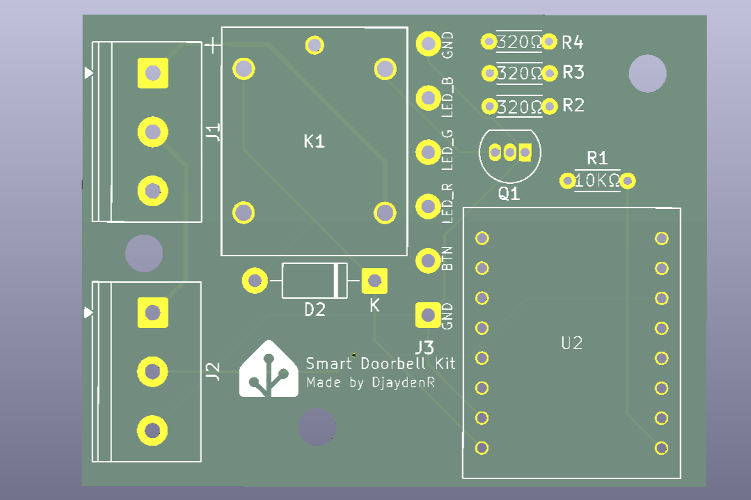
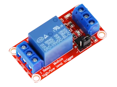
There is one tricky part however, the cheapest way I was able to get the screw terminals and the relay is by getting a module with both soldered on it. So in order to get the components you would first need to disassemble the module.
The case consists of three 3D-printed parts:
The front and back piece fit together and need to be glued. To secure the backplate you need to place heat inserts into the three holes in the case.
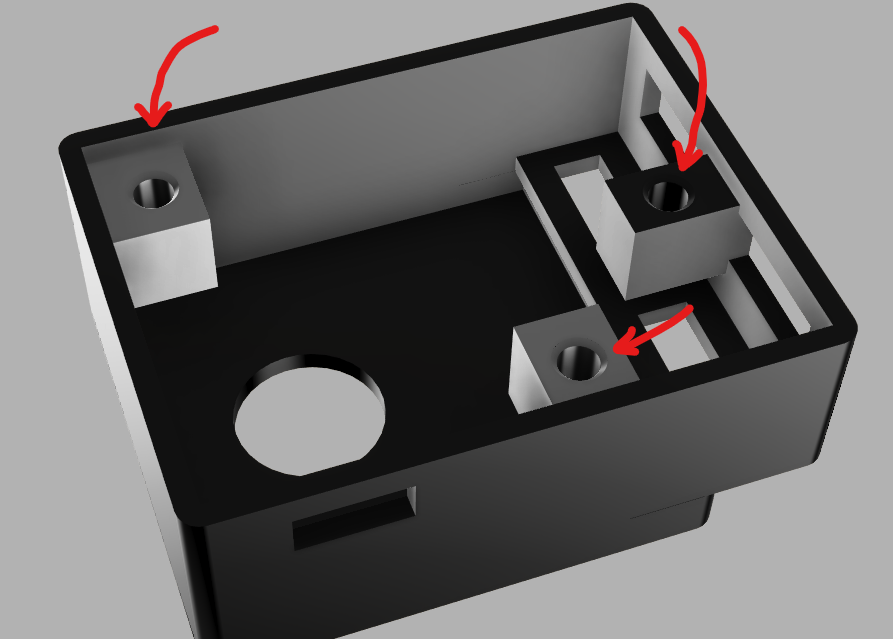
Then finally you should place the backplate on the case and put the screws through the backplate and into the inserts.
[!IMPORTANT] You must first change all the CHANGE_ME entries in the
doorbell.yamlfile
Installing the software is as easy as going to web.esphome.io, connecting the esp via a USB-cable and then uploading the doorbell.yaml file located inside the firmware folder of this repo.
Then as soon as it is done flashing you should install the device and connect it to power with a USB cable and then it should automatically be discovered inside Home Assistant under Devices & Services.
| Qty | Value | Footprint | References |
|---|---|---|---|
| 4 | R | Resistor_THT:R_Axial_DIN0204_L3.6mm_D1.6mm_P5.08mm_Horizontal | R1, R2, R3, R4 |
| 2 | Screw_Terminal_01x03 | TerminalBlock_Phoenix:TerminalBlock_Phoenix_PT-1,5-3-5.0-H_1x03_P5.00mm_Horizontal | J1, J2 |
| 1 | 1N4007 | Diode_THT:D_DO-41_SOD81_P10.16mm_Horizontal | D2 |
| 1 | Conn_01x06 | Connector_Wire:SolderWire-0.5sqmm_1x06_P4.6mm_D0.9mm_OD2.1mm | J3 |
| 1 | ESP32-C3-SuperMini | ESP32 C3 Mini:ESP32-C3-SuperMini | U2 |
| 1 | LOGO | LOGO | G*** |
| 1 | PN2222A | Package_TO_SOT_THT:TO-92_Inline | Q1 |
| 1 | SRD-05VDC-SL-C | SRD-05VDC-SL-C:RELAY_SRD-05VDC-SL-C_MCE | K1 |

rigidus/rigidus.ru
Contacts: email: i.am.rigidus טּ gmail.com jabber: rigidus@jabber.ru

ISLKey/islkey
ISLKey access-control platform — ESP32 firmware, Electron flasher, Flutter app, KiCad schematic (ISL Technologies)


IdahoLabResearch/AcCCS
A collection of tools and scripts used to communicate and emulate Electric Vehicle Communication Controllers (EVCC) and Supply Equipment Communication Controllers (SECC).

phfbertoleti/placa_lorawan
Repositório oficial da placa LoRaWAN, um kit de desenvolvimento para protótipos IoT.

fellettigiacomo/esp32-WLED-4ch-controller
Open source 4 Channel esp32-powered WLED controller with 4 relays and built in level shifter
It measures 53 × 40 mm and has 2 copper layers, 1.6 mm thick.
12 parts, built around the PN2222A and SRD-05VDC-SL-C. The full list of its parts is on this page, with links to each part's symbol and footprint where PCBKit's library has them.
From the Djayden-R/Smart-Doorbell-Kit repository on GitHub, at the commit this page was made from: the board is PCB/Doorbell_mod.kicad_pcb and its schematic PCB/Doorbell_mod.kicad_sch. PCBKit opens the board in the browser, with nothing to install.
Its repository states no licence, so its author keeps all rights: ask Djayden-R before reusing the design.