
2 layers65 × 56 mm
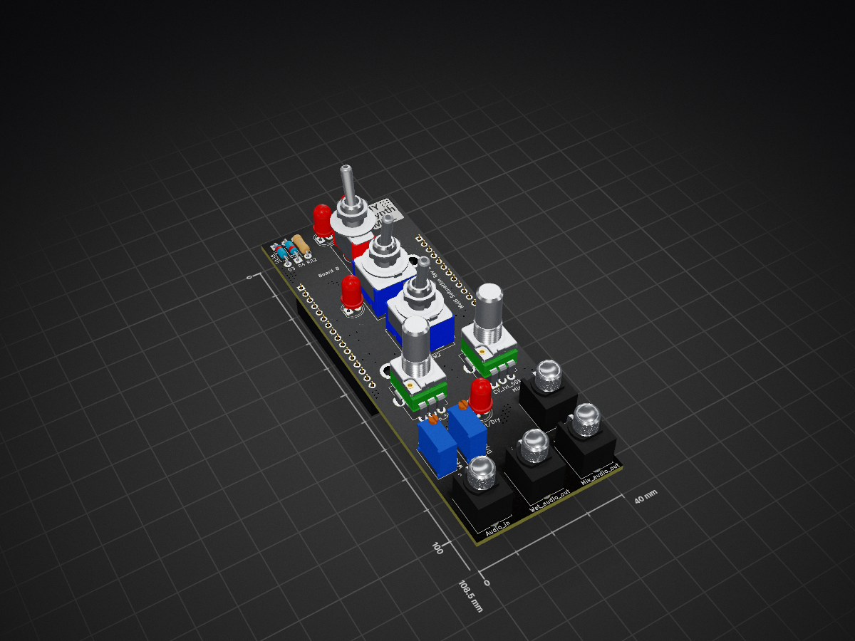
 DIYSynthMNL/Eurorack-Multi-Saturation-Module25
A multi saturation module with voltage controlled wet/dry mix
Multi saturation module board b is an open-source printed circuit board by DIYSynthMNL, from the DIYSynthMNL/Eurorack-Multi-Saturation-Module repository on GitHub, published under the GPL-3.0 licence. It is a 2-layer board of 40 × 108.5 mm with 23 parts on 36 nets, routed with 175 tracks and 146 vias.
Its parts include 6 diodes, 6 connectors, 3 switches and 1 resistor. It belongs with the audio and music boards of this library.
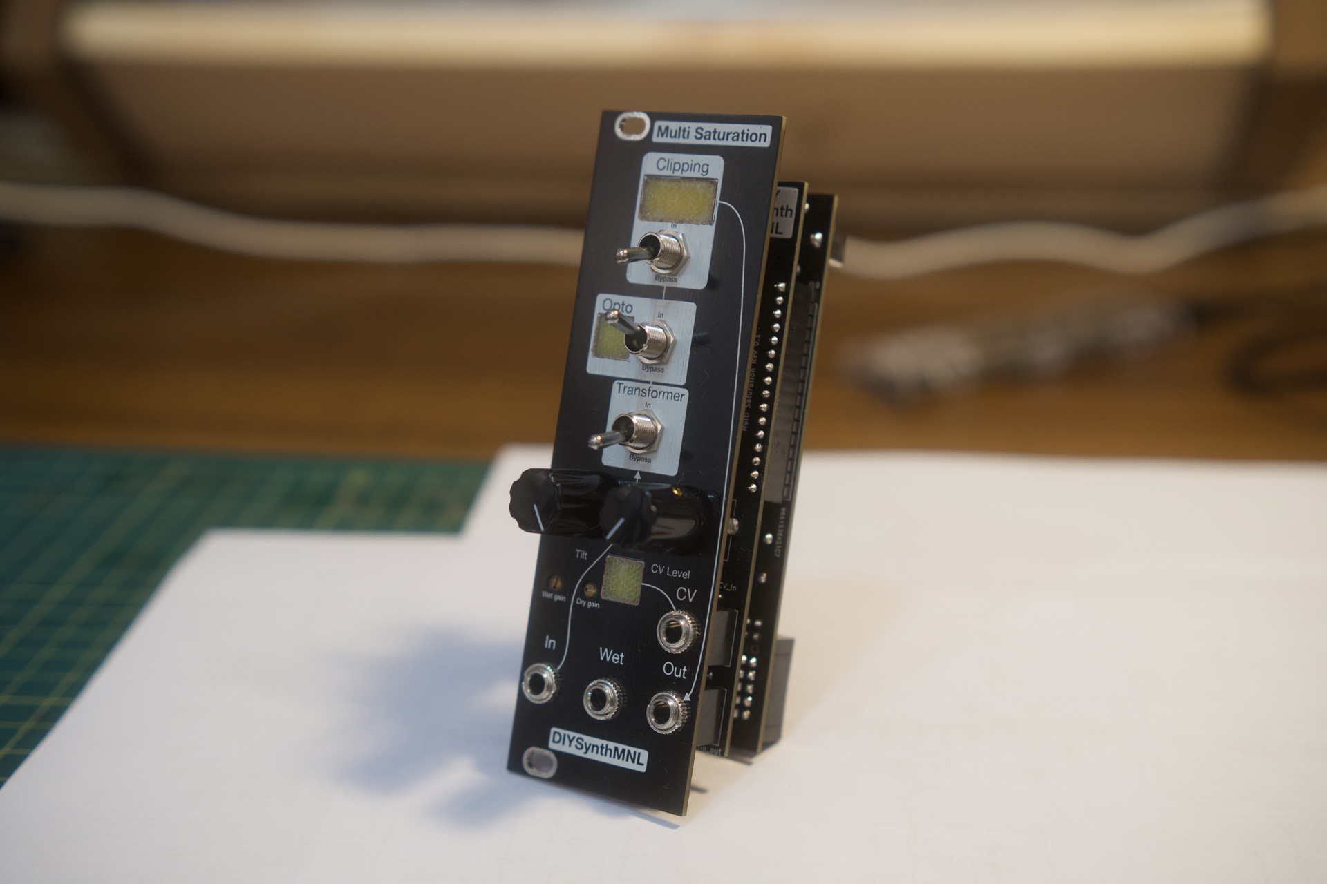
I’m designing a distortion/saturation modular synth module using different methods of distorting audio signals.
This module is a combination of transformer, opto, and clipping distortion/saturation.
Local archived copies of the borrowed-source schematics live in references/ so this repo stays useful if the upstream links die. Originals from diyrecordingequipment.com.
I got some ideas from DIYRe's Colour modules. DIYRe is a company that produces DIY kits for professional audio recording equipment. Some of their product offerings include recording studio rackmount effects.
| Colour Module | What does it do? | What ideas did you get? | Link to page | Schematic |
|---|---|---|---|---|
| CTX Transformer Colour | A transformer saturation module with a discrete opamp and a Cinemag audio transformer which has a 1:1 turns ratio. | Non-inverting amp to drive the transformer past what it can handle. Resistor before the transformer that isolates the opamp from the transformer. | https://www.diyrecordingequipment.com/products/ctx-cinemag-transformer-colour-mkii | https://cdn.shopify.com/s/files/1/0698/2265/files/CTX_mkII_Schematic.pdf?375 |
| Colourphone | A telephone sound emulator. It uses a bandpass filter and a 1:1 turn ratio audio transformer. | I have a similar transformer which is a 600:600 ohm transformer. Resistor before the transformer that isolates it from the opamp. | https://www.diyrecordingequipment.com/products/colourphone-telephone-distortion-colour | https://cdn.shopify.com/s/files/1/0698/2265/files/XQP_Colourphone_Schematic_1.3.pdf?8973696934571457842 |
| Colourupter | An opto distortion module that is vactrol based. | Using a vactrol and the circuit around it. IC1c and IC1d only. | https://www.diyrecordingequipment.com/products/colourupter | https://cdn.shopify.com/s/files/1/0698/2265/files/XQP_Colourupter_Schematic_1.7.pdf?13355729951948932441 |
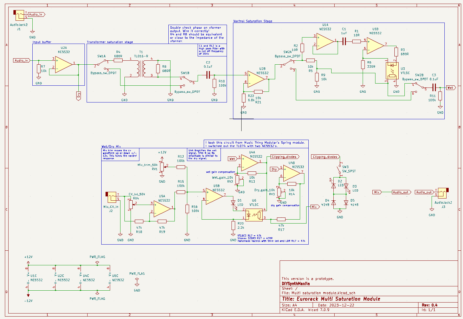
Input gain stage (buffer only, see design note below)
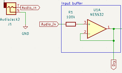
We must take into account the headroom of the op amp. The NE5532 can only output 2 volts less than the supply voltage. So for example, your supply voltage would be +/- 12V, your max output would be 10V based on the image below.

A buffer would suffice as the input stage. It would be nice to give the transformer more voltage but we wouldn’t be able to amplify the 10Vpp input to 12Vpp unless we use a +/- 15V supply.
I chose to use an NE5532 Op Amp because I believe it can drive outputs higher than TL07x.
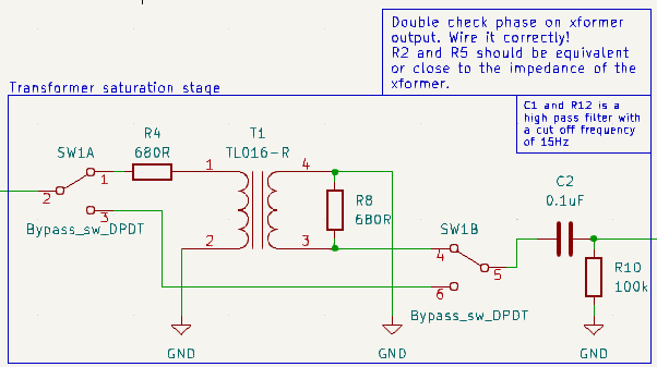
Transformer Saturation
The transformer distortion works by oversaturating the transformer’s core past what it can handle. The transformer I used would normally be used in line audio signals. A 600:600 ohm transformer. We’re using Eurorack voltage which is around 10vpp so that would oversaturate the transformer.
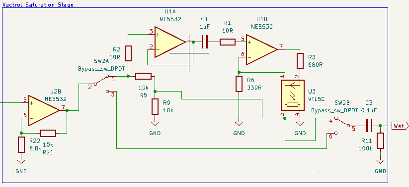
Vactrol Opto Electronic Saturation
The transformer’s output was low, I needed to add a non-inverting op amp with gain to bring the levels back to 10vpp for this stage.
I got this circuit from DIYRe’s Colourupter colour module which uses a Vactrol to clip the signal.
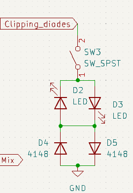
Soft Clipping Diode Saturation
I chose to place these diodes after the wet amplifier. It would be softer if I placed it before the U4A. I chained LEDs to the 1N4148s to get a softer clipping effect. LEDs alone would make saw waves looking like square waves.
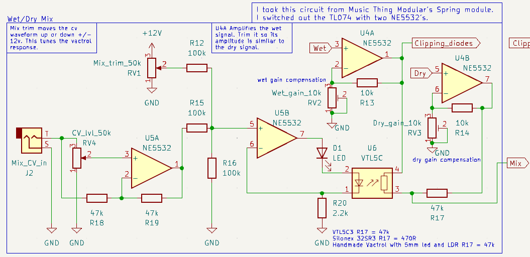
Voltage controlled Vactrol Wet/Dry mix
I used my handmade Vactrol. I made it using a 5mm diffused red LED and a 5mm LDR enclosed with black heat shrink tubing. I crimped the ends so no light would leak in. 47k works for R17 with my Vactrol.
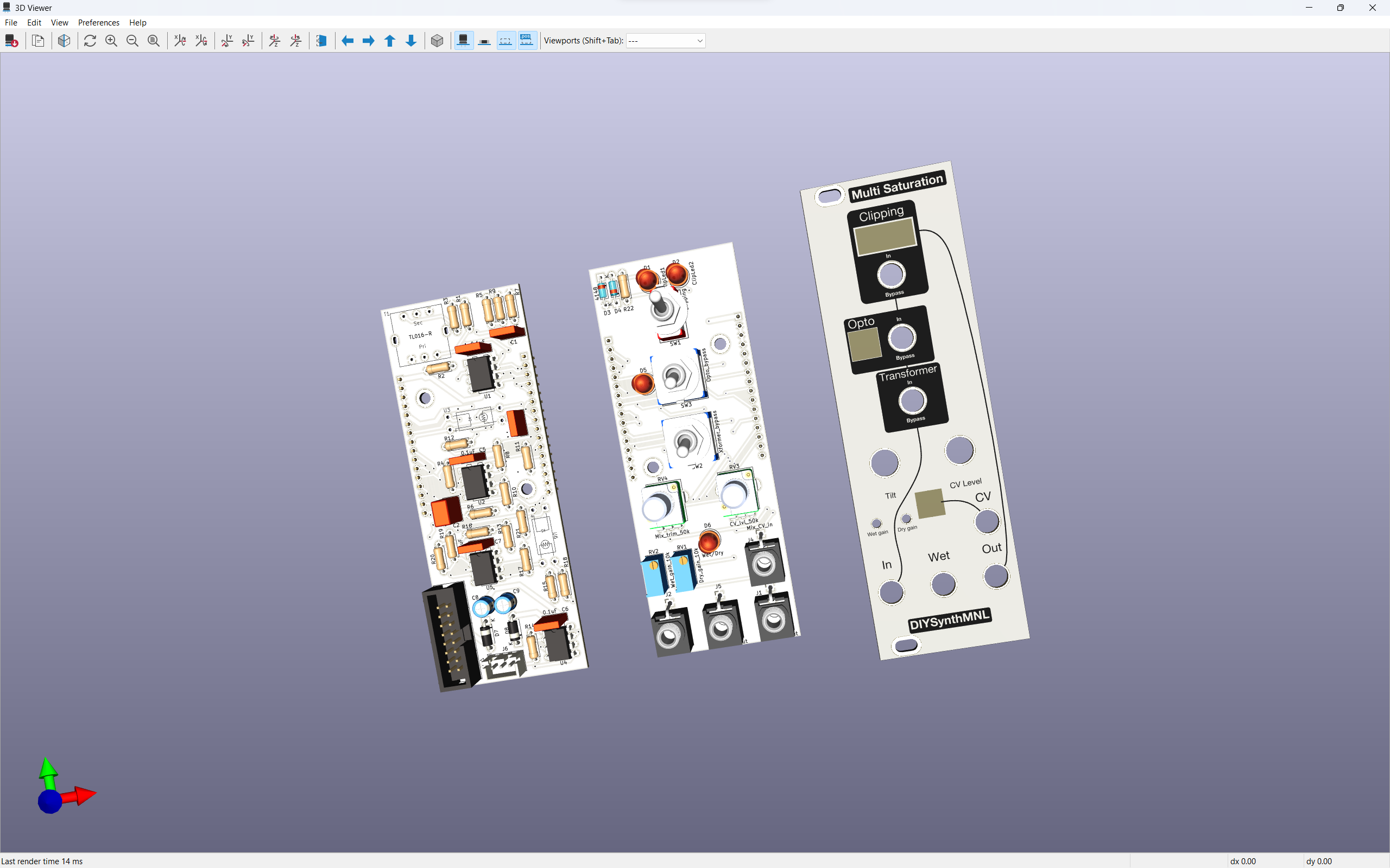
Dec 27, 2023 - Almost satisfied with the board design, rev0.1
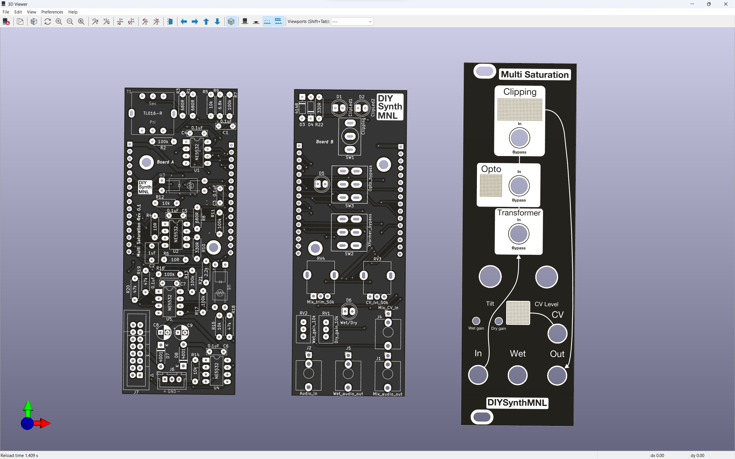
Rev 0.1 in black
Three saturation stages in series, each individually bypassable from the front panel, then a CV-controlled wet/dry mix:
Audio In ─► U1A buffer ─┬─► [Dry path → wet/dry mixer U4B]
                        │
                        └─► SW1 (Xformer bypass) ─► [TL016 transformer, 680Ω matching, HPF 15Hz]
                                                  ─► U1B buffer ─► transformer-saturated signal
                                                                     │
                                                                     ▼
                                                  SW2 (Opto bypass) ─► U2A buffer ─► C2 (1µF) ─► U2B inverting amp (gain −68)
                                                                                                    ├─► drives U3 vactrol LED (R10 limits)
                                                                                                    └─► AC-coupled out as "Wet"
                                                                                                                                ▼
                                              U4A amp ────────► clipping LEDs + 1N4148 (SW1 on Board B bypasses)
   Dry signal ──► U4B amp ───────────────────┘                                                              │
                                                                                                            ▼
                                                                                  U6 vactrol (CV wet/dry mixer, driven by Mix CV via U5A/U5B)
                                                                                                            ▼
Mix Audio Out1. Transformer saturation (TL016-R, 600:600Ω). 680Ω resistors match the transformer's characteristic impedance. Driving the primary hard pushes the magnetic core into non-linearity — classic warm "tape-like" harmonic content (mostly odd harmonics). The 15Hz HPF (C1 + R7) on the secondary removes any DC bias.
2. Opto-electronic saturation (vactrol, U3). U2B is a high-gain inverting amp (R8/R6 = 680/10 = −68× gain) driving the vactrol's LED. As the signal gets louder, the LED brightens, the LDR resistance drops, more signal shunts to ground — soft compression / saturation. Fast attack/release due to the vactrol's photo response.
3. Diode soft clipping (Board B). LEDs (D1, D2) in series with 1N4148s (D3, D4) — asymmetric soft clipping with the LEDs adding ~2V of softness before the 4148s contribute hard clip. Pleasant warmth without harsh square-wave look. SW1 on Board B bypasses.
Borrowed from Music Thing Modular's Spring reverb topology. Second vactrol (U6) acts as a CV-controlled variable resistor in the mix path. Mix CV input → U5A → U5B → vactrol LED. The Mix Trim pot (RV4, 50K) shifts the CV center point by ±12V so the vactrol's response curve aligns with your CV source (the Music Thing original optimizes for 0–5V CV; this tuning lets it handle ±5V or other ranges).
Three trim pots accessible from the front panel:
RV2 — Wet gain trim. Sets U4A's amplification of the wet (saturated) signal. Goal: match the wet signal's amplitude to the dry signal so the mix knob crossfades cleanly.
RV3 — Dry gain trim. Sets U4B's amplification of the dry signal. Adjust together with RV2 until at the mix midpoint, the output amplitude doesn't jump as you switch saturation stages on/off.
RV4 — Mix trim. Shifts the Mix CV bias up or down ±12V. Adjust until the panel mix pot's full clockwise position gives 100% wet and full counter-clockwise gives 100% dry, with your CV source connected. With no CV connected (or 0V), midpoint should give 50/50.
Procedure:
What's ready for builders today, and what's still on the TODO list:
Production assets (what you need to actually fabricate and assemble a final unit)
kicad/Separate boards/rev 0.1/; rev 0.2 fixes pending (see PCB revisions in readme)Prototype assets (for breadboard / perfboard / 3D-printed-panel builds before final PCB)
Documentation
Want to help fill a gap (build photos, gerbers, an assembly guide)? Open an issue or PR.
| Qty | Value | Footprint | References |
|---|---|---|---|
| 2 | 4148 | DIYSynthMNL:D_4148_BigPads | D3, D4 |
| 2 | MountingHole | DIYSynthMNL:MountingHole_M3_Standoff_Pad | H3, H4 |
| 1 | 330R | DIYSynthMNL:R_quarter_watt_L6.3mm_D2.5mm_P7.62mm | R22 |
| 1 | Audio_in | DIYSynthMNL:AudioJack_3.5mm_long_pads | J2 |
| 1 | Board | PCM_kikit:Board | B2 |
| 1 | Board_B_1 | Connector_PinSocket_2.54mm:PinSocket_1x16_P2.54mm_Vertical | J8 |
| 1 | Board_B_2 | Connector_PinSocket_2.54mm:PinSocket_1x16_P2.54mm_Vertical | J9 |
| 1 | CV_lvl_50k | DIYSynthMNL:Potentiometer_RV09_BigPads | RV3 |
| 1 | ClipLed1 | DIYSynthMNL:LED_D5.0mm_BigPads | D1 |
| 1 | ClipLed2 | DIYSynthMNL:LED_D5.0mm_BigPads | D2 |
| 1 | Clipping | DIYSynthMNL:ToggleSwitch_MTS-102_SPDT | SW1 |
| 1 | Dry_gain_10k | DIYSynthMNL:Potentiometer_Bourns_3296W_Vertical_BigPads | RV1 |
| 1 | Mix_CV_in | DIYSynthMNL:AudioJack_3.5mm_long_pads | J4 |
| 1 | Mix_audio_out | DIYSynthMNL:AudioJack_3.5mm_long_pads | J1 |
| 1 | Mix_trim_50k | DIYSynthMNL:Potentiometer_RV09_BigPads | RV4 |
| 1 | Opto_bypass | DIYSynthMNL:ToggleSwitch_MTS-202_DPDT | SW3 |
| 1 | Opto_sat | DIYSynthMNL:LED_D5.0mm_BigPads | D5 |
| 1 | Wet/Dry | DIYSynthMNL:LED_D5.0mm_BigPads | D6 |
| 1 | Wet_audio_out | DIYSynthMNL:AudioJack_3.5mm_long_pads | J5 |
| 1 | Wet_gain_10k | DIYSynthMNL:Potentiometer_Bourns_3296W_Vertical_BigPads | RV2 |
| 1 | Xformer_bypass | DIYSynthMNL:ToggleSwitch_MTS-202_DPDT | SW2 |

google/mozc-devices
Circuit diagrams and firmware source code for Gboard DIY keyboards


Duet3D/Duet-2-Hardware
The KiCAD source for the Duet 3d printer controller see www.duet3d.com
It measures 40 × 108.5 mm and has 2 copper layers, 1.6 mm thick.
23 parts. The full list of its parts is on this page, with links to each part's symbol and footprint where PCBKit's library has them.
From the DIYSynthMNL/Eurorack-Multi-Saturation-Module repository on GitHub, at the commit this page was made from: the board is kicad/Separate boards/rev 0.1/Multiboard_Separate_Board_B/Multi saturation module_board_b.kicad_pcb and its schematic kicad/Multi saturation module.kicad_sch. PCBKit opens the board in the browser, with nothing to install.
Its repository publishes it under the GPL-3.0 licence: you may reuse it on that licence's terms (keep the author's notice, and for a copyleft licence share your changes alike).