2 layers146 × 70 mm
Eurobusboard idc jst 8
DIYSynthMNL/EuroBusboard
A Eurorack Bus Board that has 8 outputs
40 parts3GPL-3.0

 DIYSynthMNL/EuroBusboard3
A Eurorack Bus Board that has 8 outputs
EuroBusboard is an open-source printed circuit board by DIYSynthMNL, from the DIYSynthMNL/EuroBusboard repository on GitHub, published under the GPL-3.0 licence. It is a 2-layer board of 196 × 137.7 mm with 90 parts on 21 nets, routed with 122 tracks and 719 vias.
Its parts include 42 connectors, 12 diodes, 6 capacitors and 6 resistors. It belongs with the audio and music boards of this library.
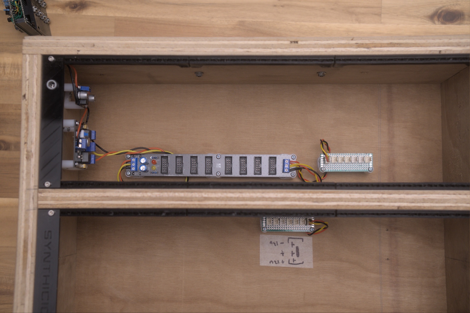
A Eurorack bus board with 8 module slots, distributing ±12V + GND across multiple connector formats. The project has three PCB variants in the same KiCad project: 10-pin IDC + JST combined, 10-pin IDC only, and JST only.
For the Doepfer-standard 16-pin IDC variant (with
+5V,CV,Gaterails additionally distributed), see the sibling repo: EuroBusboard-8-IDC-16PIN.
The KiCad project contains four configurations. Pick one when fabricating the PCB:
| Variant | KiCad file | Per-slot connectors | Use case |
|---|---|---|---|
| 16-pin IDC (Doepfer A-100) | (in separate repo: EuroBusboard-8-IDC-16PIN) | 1× 16-pin IDC | Modules with full Doepfer ribbon cables (±12V + GND + +5V + CV + Gate) |
| 10-pin IDC + JST (combined) | eurobusboard_idc_jst_8.kicad_pcb | 1× 10-pin IDC + 1× 3-pin JST | Maximum flexibility — accepts both connector types per slot |
| 10-pin IDC only | eurobusboard_idc_8.kicad_pcb | 1× 10-pin IDC | Compact, IDC-only modules |
| JST only | eurobusboard_jst_8.kicad_pcb | 1× 3-pin JST | DIY modules that use only the 3-pin JST power input |
All variants share the same power-input + reverse-protection + filter section. Only the per-slot connectors differ.
Looking at the IDC connector with the keyway (red stripe) on the bottom:
Pin   10  9   8   7   6   5   4   3   2   1
      +12 +12 GND GND GND GND GND GND -12 -12
-12V is on pin 1 / 2 (the red-stripe side) — Eurorack convention. +12V is on pin 9 / 10 (opposite side). Six GND pins in the middle provide low-impedance ground return.
The 3-pin JST is:
| JST pin | Net |
|---|---|
| 1 | +12V |
| 2 | GND |
| 3 | -12V |
Same circuit on all three sheets, just renamed nets per variant:
External ±12V supply
   │
   ├──[D3 / D14 / D9   1N4007 reverse-polarity diode on +12V]──┬── +12V bus
   │                                                            │
   │                                                            [C1 / C7 / C5   100µF bulk cap]
   │                                                            │
   │                                                            [D1 / D13 / D11  +12V indicator LED + R1/R7/R5 10K]
   │
   └──[D4 / D16 / D10  1N4007 reverse-polarity diode on -12V]──┬── -12V bus
                                                                │
                                                                [C2 / C8 / C6   100µF bulk cap]
                                                                │
                                                                [D2 / D15 / D12  -12V indicator LED + R2/R8/R6 10K]
Additional features (combined-variant only):
1N4007 diodes have a real voltage drop. At a peak transient current of 1 A across each rail (with all 8 modules pulling momentarily), the diode drops about 1.0 V — modules see only ~11 V on the rail instead of 12 V. For most analog modules this is harmless; for tight regulators (e.g. an LM7805 regulating to +5V from +12V supply that's actually 11V), it can reduce headroom. A 1N5817 Schottky (~0.4 V drop) would be a near-drop-in upgrade. See issue.
No +5V or CV/Gate rails. The 10-pin IDC variants don't distribute +5V (which most digital modules need) or CV/Gate (which the Doepfer A-100 standard provides for keyboard-bus signals). Modules requiring +5V must generate their own (via a 78M05 + the +12V rail — which is what most DIYSynthMNL modules do). For full Doepfer compatibility, use the 16-pin IDC variant in EuroBusboard-8-IDC-16PIN.
Bulk capacitance. 100 µF at the input is reasonable for a small case. For a fully-loaded board with current-hungry modules (digital sequencers, OLEDs, several VCAs), consider adding ~10 µF ceramics near each IDC connector for transient suppression.
GPLv3 — strong copyleft. Note: this is different from most DIYSynthMNL modules (which use CC-BY-NC-SA 4.0 for hardware, MIT for firmware). Confirm this license is intentional — for a passive bus board, MIT or CC-BY-SA may be more appropriate. See issue.
What's ready for builders today, and what's still on the TODO list:
kicad/, no rev marker yet| Qty | Value | Footprint | References |
|---|---|---|---|
| 18 | MountingHole_Pad | DIYSynthMNL:MountingHole_M3_Standoff_Pad | H1, H2, H3, H4, H5, H6, H7, H10, H11, H12, H13, H14, H15, H16, H17, H18 +2 |
| 6 | 100uF | Capacitor_THT:CP_Radial_D8.0mm_P3.50mm | C1, C2, C5, C6, C7, C8 |
| 6 | 10K | DIYSynthMNL:R_quarter_watt_L6.3mm_D2.5mm_P7.62mm | R1, R2, R5, R6, R7, R8 |
| 6 | 4007 | DIYSynthMNL:D_DO-41_SOD81_P7.62mm_Horizontal_BigPads | D3, D4, D9, D10, D14, D16 |
| 3 | +12V | DIYSynthMNL:LED_D5.0mm_BigPads | D1, D11, D13 |
| 3 | -12V | DIYSynthMNL:LED_D5.0mm_BigPads | D2, D12, D15 |
| 3 | Board | PCM_kikit:Board | B1, B2, B3 |
| 3 | Power In | DIYSynthMNL:TerminalBlock_MetzConnect_Type101_RT01603HBWC_1x03_P5.08mm_Horizontal | J1, J41, J43 |
| 2 | IDC1 | DIYSynthMNL:IDC-Header_2x05_P2.54mm_Vertical_BigPads | J2, J23 |
| 2 | IDC2 | DIYSynthMNL:IDC-Header_2x05_P2.54mm_Vertical_BigPads | J4, J24 |
| 2 | IDC3 | DIYSynthMNL:IDC-Header_2x05_P2.54mm_Vertical_BigPads | J6, J25 |
| 2 | IDC4 | DIYSynthMNL:IDC-Header_2x05_P2.54mm_Vertical_BigPads | J8, J26 |
| 2 | IDC5 | DIYSynthMNL:IDC-Header_2x05_P2.54mm_Vertical_BigPads | J10, J27 |
| 2 | IDC6 | DIYSynthMNL:IDC-Header_2x05_P2.54mm_Vertical_BigPads | J12, J28 |
| 2 | IDC7 | DIYSynthMNL:IDC-Header_2x05_P2.54mm_Vertical_BigPads | J14, J29 |
| 2 | IDC8 | DIYSynthMNL:IDC-Header_2x05_P2.54mm_Vertical_BigPads | J16, J30 |
| 2 | JST1 | DIYSynthMNL:Eurorack_power_jst_3P | J3, J33 |
| 2 | JST2 | DIYSynthMNL:Eurorack_power_jst_3P | J5, J34 |
| 2 | JST3 | DIYSynthMNL:Eurorack_power_jst_3P | J7, J35 |
| 2 | JST4 | DIYSynthMNL:Eurorack_power_jst_3P | J9, J36 |
| 2 | JST5 | DIYSynthMNL:Eurorack_power_jst_3P | J11, J37 |
| 2 | JST6 | DIYSynthMNL:Eurorack_power_jst_3P | J13, J38 |
| 2 | JST7 | DIYSynthMNL:Eurorack_power_jst_3P | J15, J39 |
| 2 | JST8 | DIYSynthMNL:Eurorack_power_jst_3P | J17, J40 |
| 2 | Power out | DIYSynthMNL:TerminalBlock_MetzConnect_Type101_RT01603HBWC_1x03_P5.08mm_Horizontal | J42, J44 |
| 1 | +12V | TestPoint:TestPoint_THTPad_2.0x2.0mm_Drill1.0mm | TP1 |
| 1 | -12V | TestPoint:TestPoint_THTPad_2.0x2.0mm_Drill1.0mm | TP3 |
| 1 | GND | TestPoint:TestPoint_THTPad_2.0x2.0mm_Drill1.0mm | TP2 |
| 1 | Power In | DIYSynthMNL:IDC-Header_2x05_P2.54mm_Vertical_BigPads | J22 |
| 1 | Power In | DIYSynthMNL:Eurorack_power_jst_3P | J19 |
| 1 | Power Thru | DIYSynthMNL:IDC-Header_2x05_P2.54mm_Vertical_BigPads | J21 |
| 1 | Power thru | DIYSynthMNL:TerminalBlock_MetzConnect_Type101_RT01603HBWC_1x03_P5.08mm_Horizontal | J18 |
| 1 | Power thru | DIYSynthMNL:Eurorack_power_jst_3P | J20 |
DIYSynthMNL/EuroBusboard
A Eurorack Bus Board that has 8 outputs


carrefinho/forager
34-key wireless split keyboard inspired by ZSA Voyager

PantsForBirds/adsbee
Open Source Embedded ADS-B Receiver


siderakb/ergo-snm-keyboard
ErgoSNM is a split ergonomic keyboard integrated with trackball, wireless is in beta

zynthian/zynthian-hw
Zynthian hardware stuff: PCBs, schemes, parts specifications, pin assignment, ...

It measures 196 × 137.7 mm and has 2 copper layers, 1.6 mm thick.
90 parts. The full list of its parts is on this page, with links to each part's symbol and footprint where PCBKit's library has them.
From the DIYSynthMNL/EuroBusboard repository on GitHub, at the commit this page was made from: the board is kicad/EuroBusboard.kicad_pcb and its schematic kicad/EuroBusboard.kicad_sch. PCBKit opens the board in the browser, with nothing to install.
Its repository publishes it under the GPL-3.0 licence: you may reuse it on that licence's terms (keep the author's notice, and for a copyleft licence share your changes alike).