
2 layers60 × 30 mm
Controller
google/mozc-devices
Circuit diagrams and firmware source code for Gboard DIY keyboards
11 parts3kApache-2.0

A low-voltage AC-to-DC power supply PCB designed and developed in KiCad.
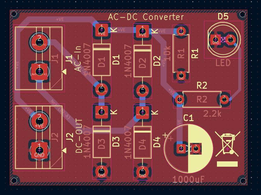
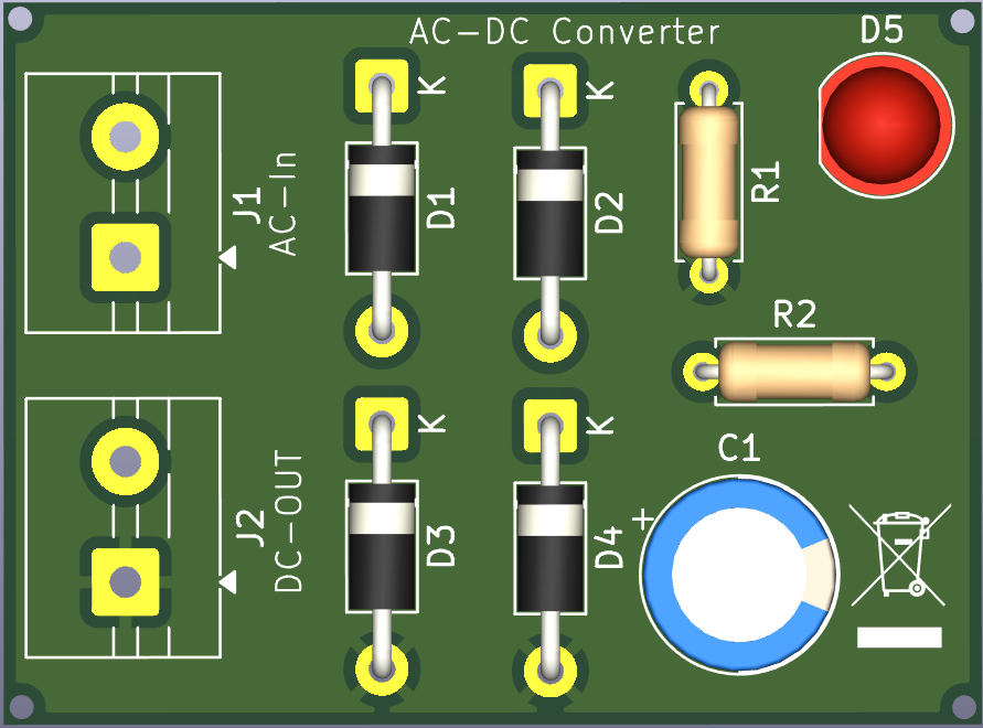
ACDC is an open-source printed circuit board by CraftsmanSJ, from the CraftsmanSJ/AC-DC-Converter repository on GitHub. It is a 2-layer board of 40.5 × 29.9 mm with 11 parts on 5 nets, routed with 27 tracks and 0 vias.
Its parts include 5 diodes, 2 resistors, 2 connectors and 1 capacitor.
A low-voltage AC-to-DC power supply PCB designed and developed in KiCad.
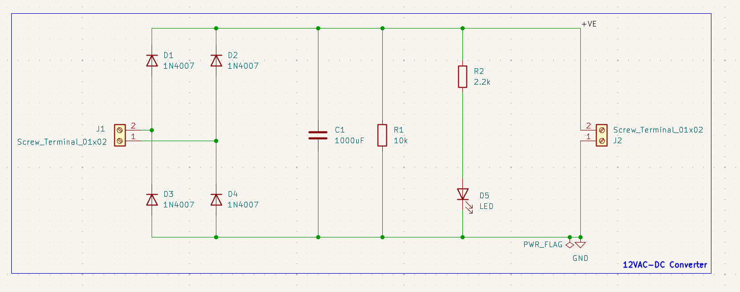
This project is a 12V AC to DC converter designed as a practical PCB design project. The circuit uses a full-wave bridge rectifier followed by a 1000µF smoothing capacitor to convert the AC input into filtered DC.
The board also includes a 10kΩ bleeder resistor for the filter capacitor and a 2.2kΩ resistor with an LED for power indication.
| Reference | Component | Value |
|---|---|---|
| D1–D4 | Rectifier Diodes | 1N4007 |
| C1 | Electrolytic Capacitor | 1000µF |
| R1 | Bleeder Resistor | 10kΩ |
| R2 | LED Resistor | 2.2kΩ |
| D5 | LED | Power Indicator |
| J1 | Screw Terminal | AC Input |
| J2 | Screw Terminal | DC Output |
The 12V AC input is converted into pulsating DC through the four-diode full-wave bridge rectifier. The 1000µF capacitor then smooths the rectified waveform and reduces the output ripple.
The 10kΩ resistor provides a discharge path for the filter capacitor, while the LED provides a visual indication that the DC rail is energized.
The PCB was designed completely in KiCad, including schematic capture, footprint assignment, component placement, routing, and design-rule verification.
The design process was:
Schematic → Components → Footprints → PCB Placement → Routing → DRC → Final PCB
This project was created to gain practical experience with:
This project is intended for use with a suitable low-voltage 12V AC source.
Do not connect the input directly to mains voltage.
Santanu Jha
Embedded Systems | Electronics | PCB Design
| Qty | Value | Footprint | References |
|---|---|---|---|
| 4 | 1N4007 | Diode_THT:D_DO-41_SOD81_P10.16mm_Horizontal | D1, D2, D3, D4 |
| 2 | Screw_Terminal_01x02 | TerminalBlock:TerminalBlock_MaiXu_MX126-5.0-02P_1x02_P5.00mm | J1, J2 |
| 1 | 1000uF | Capacitor_THT:CP_Radial_D8.0mm_P2.50mm | C1 |
| 1 | 10k | Resistor_THT:R_Axial_DIN0207_L6.3mm_D2.5mm_P7.62mm_Horizontal | R1 |
| 1 | 2.2k | Resistor_THT:R_Axial_DIN0207_L6.3mm_D2.5mm_P7.62mm_Horizontal | R2 |
| 1 | LED | LED_THT:LED_D5.0mm | D5 |
The 10 most common of 11 parts.
google/mozc-devices
Circuit diagrams and firmware source code for Gboard DIY keyboards


FrameworkComputer/ExpansionCards
Reference designs and documentation to create Expansion Cards for the Framework Laptop

hoglet67/RGBtoHDMI
Bare-metal Raspberry Pi project that provides pixel-perfect sampling of Retro Computer RGB/YUV video and conversion to HDMI

hackclub/OnBoard
💡 Join 1,000 teenagers and make your first PCB with a $100 grant!


tardate/LittleArduinoProjects
a collection of "Little Electronic & Arduino Projects", most involving electronics or an Arduino in one way or another!

basilfx/TRADFRI-Hacking
Hacking IKEA TRÅDFRI products, such as light bulbs, window blinds and other accessories.
It measures 40.5 × 29.9 mm and has 2 copper layers, 1.6 mm thick.
11 parts. The full list of its parts is on this page, with links to each part's symbol and footprint where PCBKit's library has them.
From the CraftsmanSJ/AC-DC-Converter repository on GitHub, at the commit this page was made from: the board is ACDC/ACDC.kicad_pcb and its schematic ACDC/ACDC.kicad_sch. PCBKit opens the board in the browser, with nothing to install.
Its repository states no licence, so its author keeps all rights: ask CraftsmanSJ before reusing the design.