

2 layers40 × 20 mm

Converting a manual Skywatcher EQ4 equatorial mount into a fully computerized GoTo mount using OnStepX firmware on an ESP32 microcontroller.
Onstep is an open-source printed circuit board by Cosmiccirkit01, from the Cosmiccirkit01/OnStepX-Eq4 repository on GitHub, published under the GPL-3.0 licence. It is a 2-layer board of 90 × 78.5 mm with 13 parts on 49 nets, routed with 202 tracks and 0 vias.
It is built around the EEUFC1H101. Its parts include 2 ICs and 2 connectors. It belongs with the ESP32 boards of this library.
Converting a manual Skywatcher EQ4 equatorial mount into a fully computerized GoTo mount using OnStepX firmware on an ESP32 microcontroller.
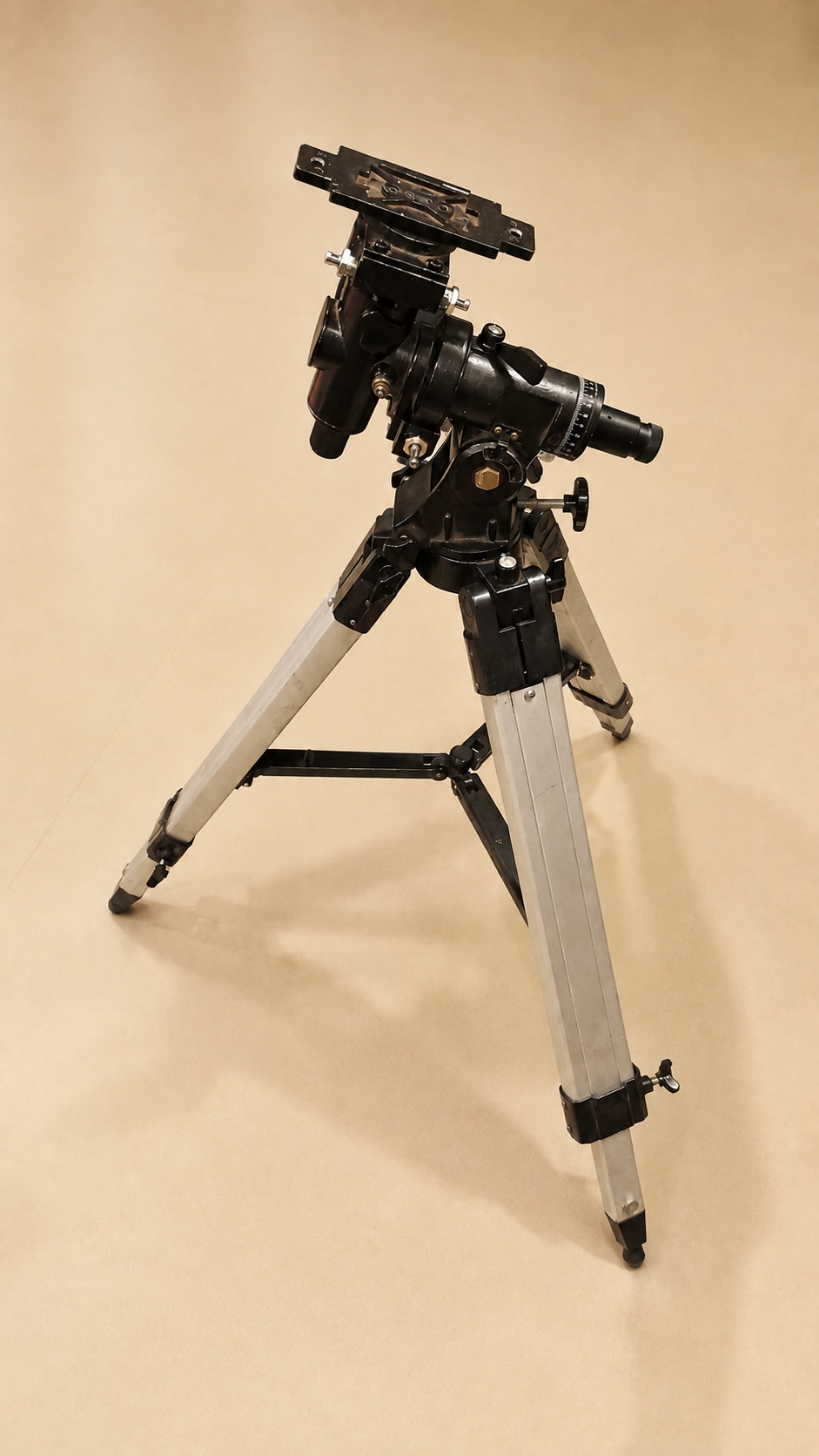
OnStepX is an open-source, computerized GoTo controller for telescope mounts, built around stepper motors. It supports both Equatorial and Alt/Az mounts and runs on a range of microcontrollers (ESP32, STM32 Blue Pill/Black Pill, Fysetc boards, Teensy, etc.).
This project documents converting a stock EQ4 equatorial mount into a GoTo mount using an ESP32, custom-built stepper driver electronics, and a 3D-printed mount for the electronics. It covers everything from flashing the firmware to designing a custom PCB to machining brackets for motors that the mount was never designed to hold.
Note: This is a personal build log, not an official OnStepX guide. Some steps (such as pin assignments and gear ratios) are specific to this hardware combination and may need to be adapted for other mounts or driver boards.
| Component | Notes | Link |
|---|---|---|
| Digital Multimeter | For voltage/continuity checks | Link |
| Breadboard (840 tie points) | For initial circuit testing | Link |
| ESP32 (ESP-WROOM-32) | Main microcontroller | Link |
| NEMA17 Stepper Motor | 200 steps/rev, one per axis | Link |
| DRV8825 Motor Driver | One per axis (see driver comparison) | Link |
| Electrolytic Capacitor (100µF, 50V) | Protects driver from voltage spikes | Link |
| Jumper Cables (M2M) | Breadboard wiring | Link |
| Power Source: 12V, 2A (or 12V, 5A) | 2A is sufficient for testing; upgrade to 5A if needed | 2A · 5A |
| Active Buzzer | Status indication | Link |
| Step-Down Buck Converter | Steps 12V down to 5V for the driver FLT pin | Link |
| 4-Pin Aviation Connectors | Detachable motor/power connections | Link |
| L-shaped brackets (NEMA17) | Mounting motors to the axes | Link |
| GT2 Pulleys (60T & 12T) | 5:1 gear ratio | 60T · 12T |
| GT2 Timing Belt | Closed-loop, 180mm | Link |
Download the OnStepX firmware from the official GitHub repository — use the main branch for the latest configuration. Latest version for this build: 10.28.
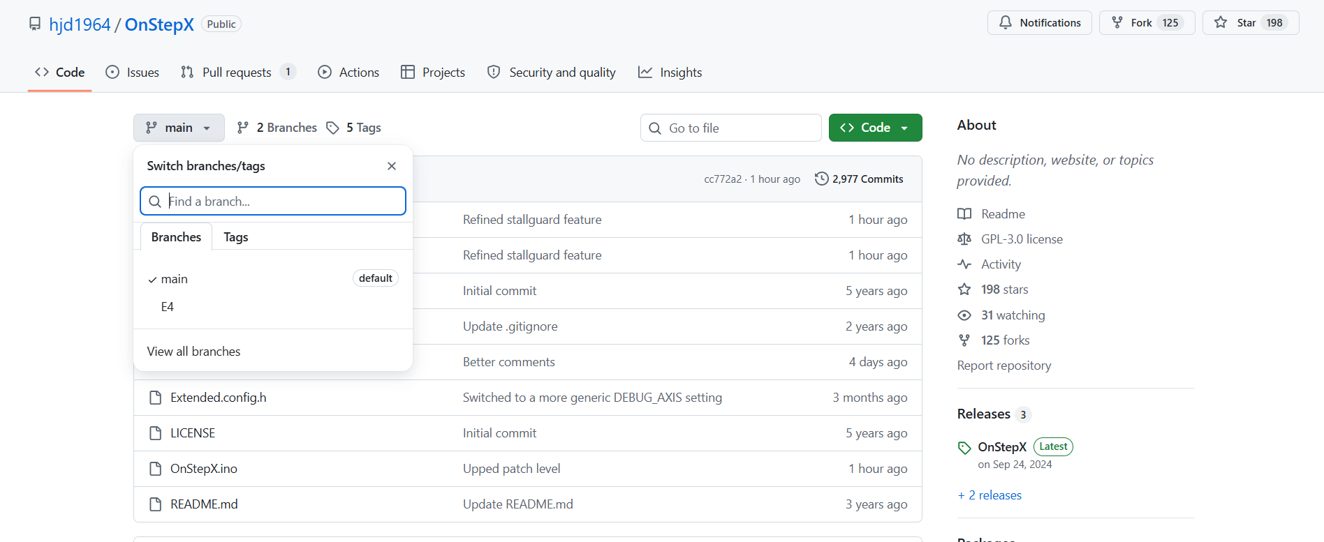 Credits: hjd1964
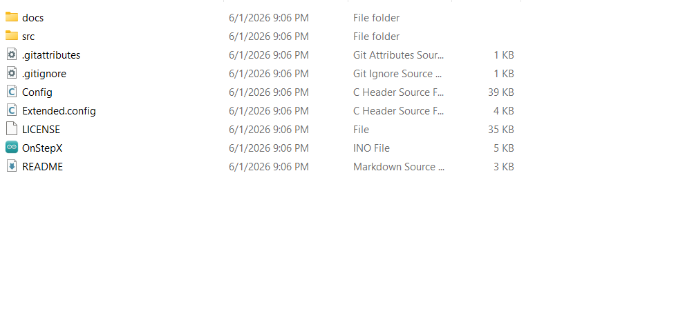
Unzip the downloaded file (it extracts as OnStepX-main) and rename the folder to OnStepX.
Open the folder — it should contain the following files:
Open the OnStepX.ino file. This launches Arduino IDE along with the Config.h and Extended.config.h files alongside it.
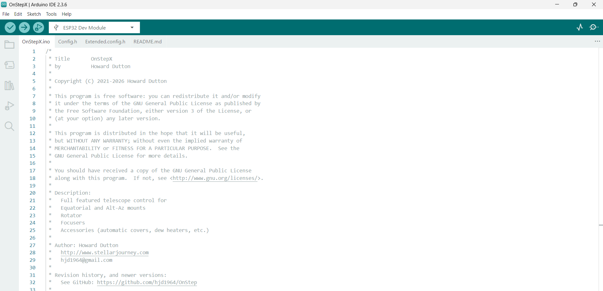
If you don't have Arduino IDE installed, download it from the official website.
Install the ESP32 USB driver. The ESP32 dev board uses a CP210x USB-to-UART chip, which needs an external driver on most systems. Follow this driver installation guide if needed.
Add the ESP32 board package to Arduino IDE:
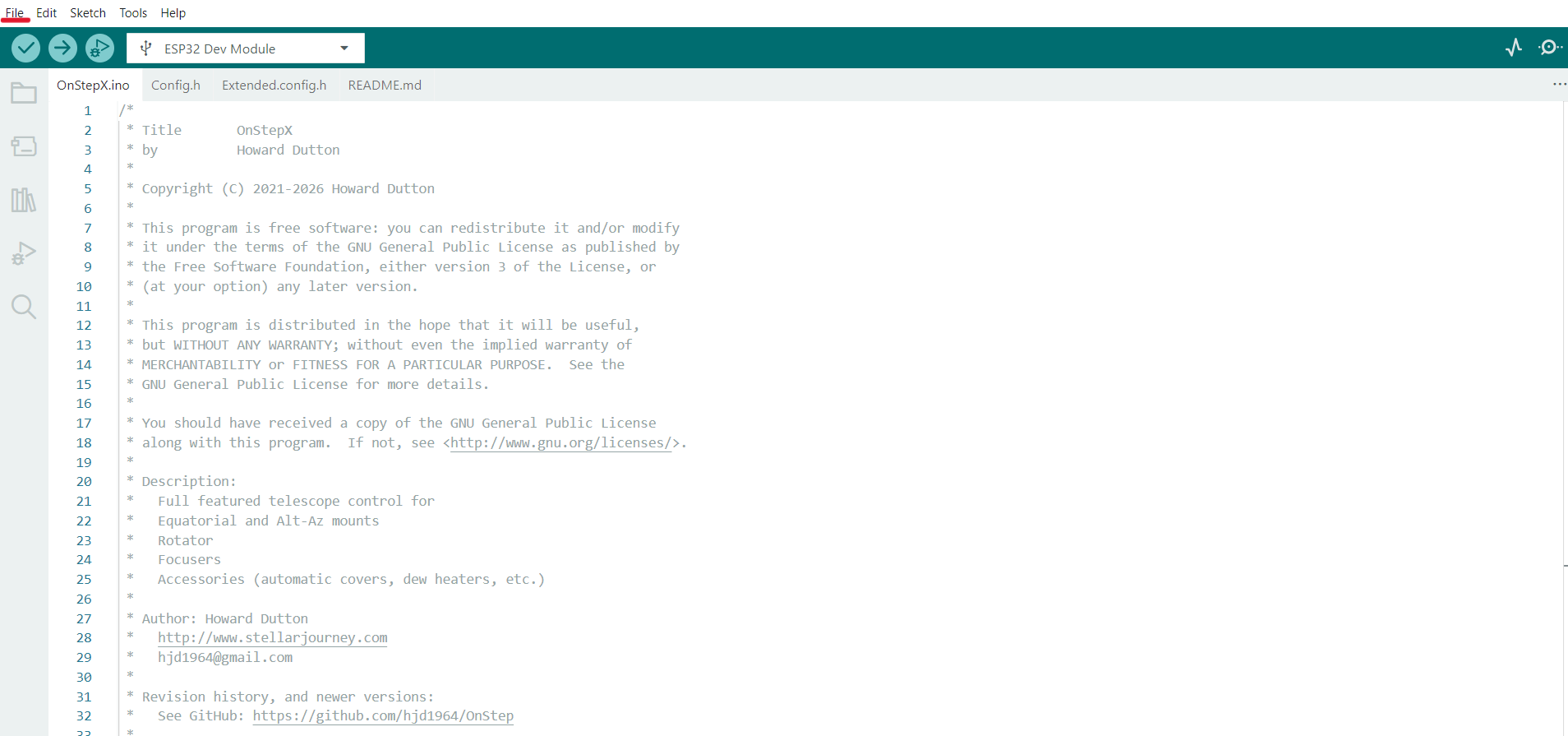
Go to File
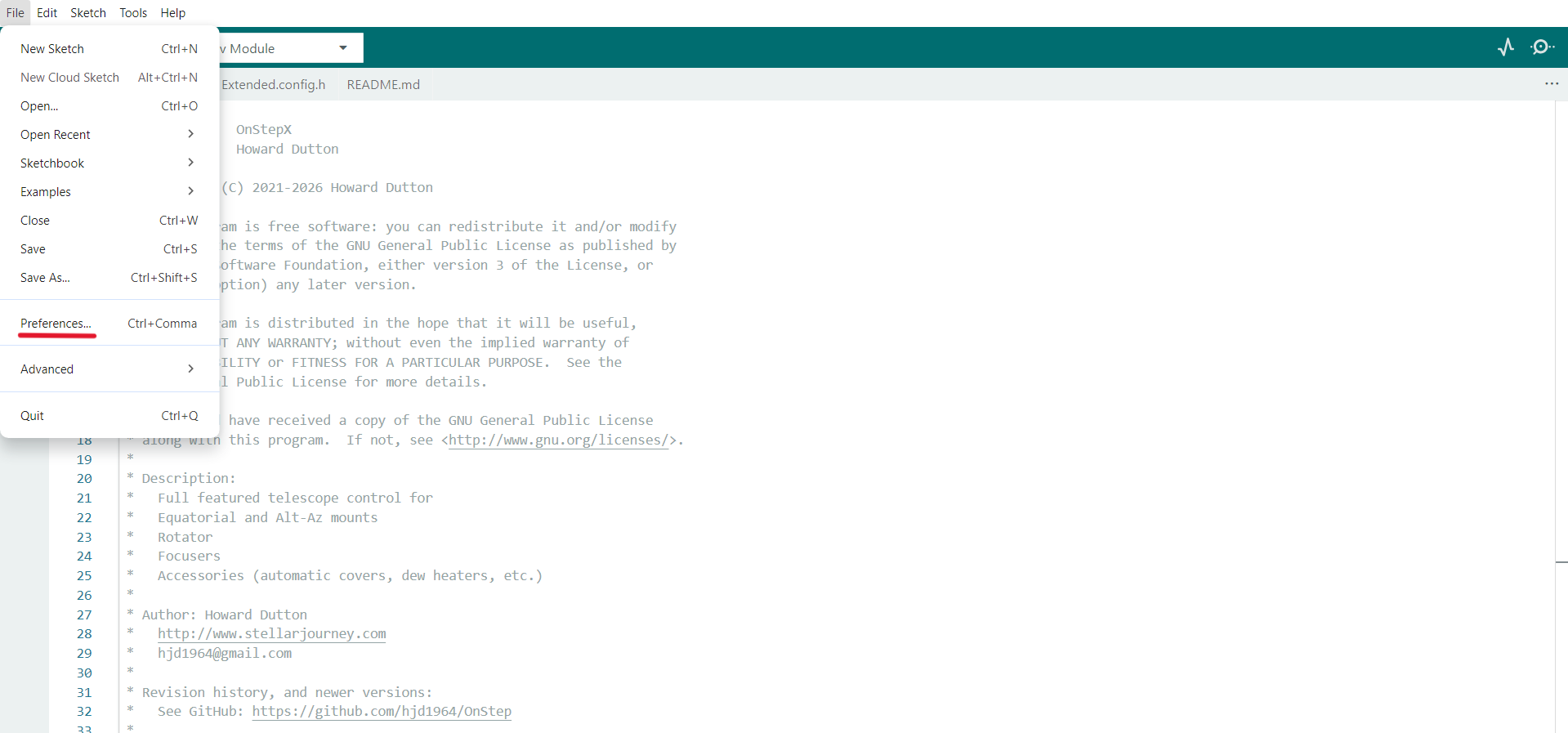
Go to Preferences
In the Preferences window, paste the following URL into Additional Boards Manager URLs, then click OK:
https://raw.githubusercontent.com/espressif/arduino-esp32/gh-pages/package_esp32_index.json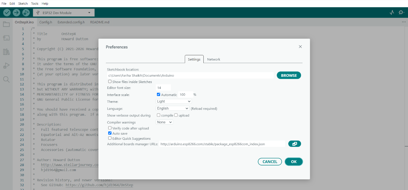
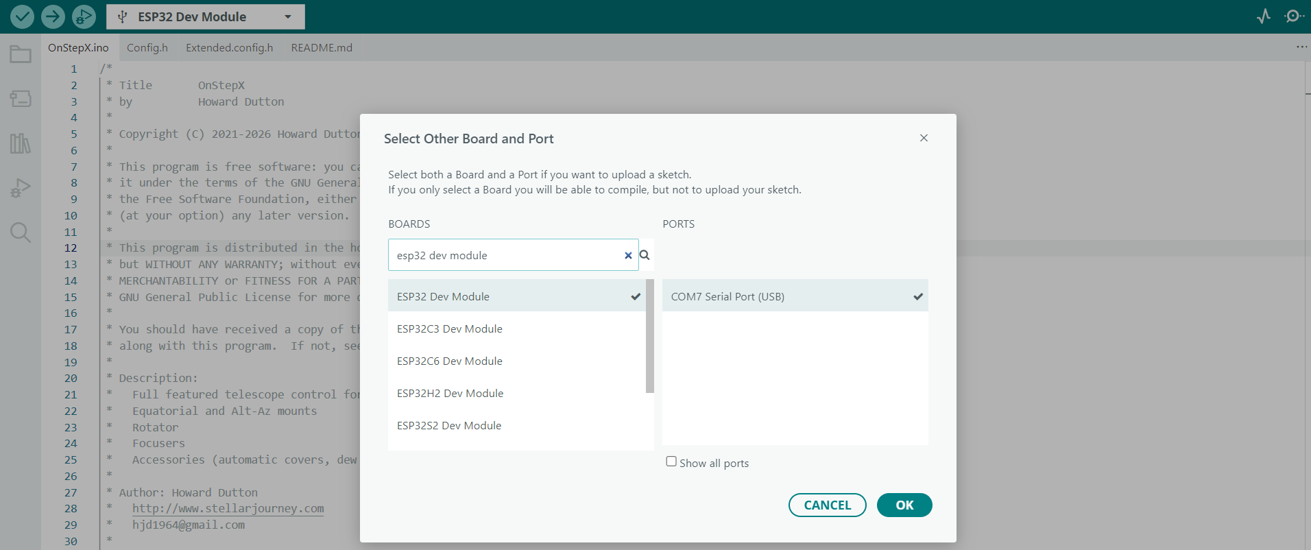
Select the board and port. Click the board/port dropdown and choose "Select other board and port".
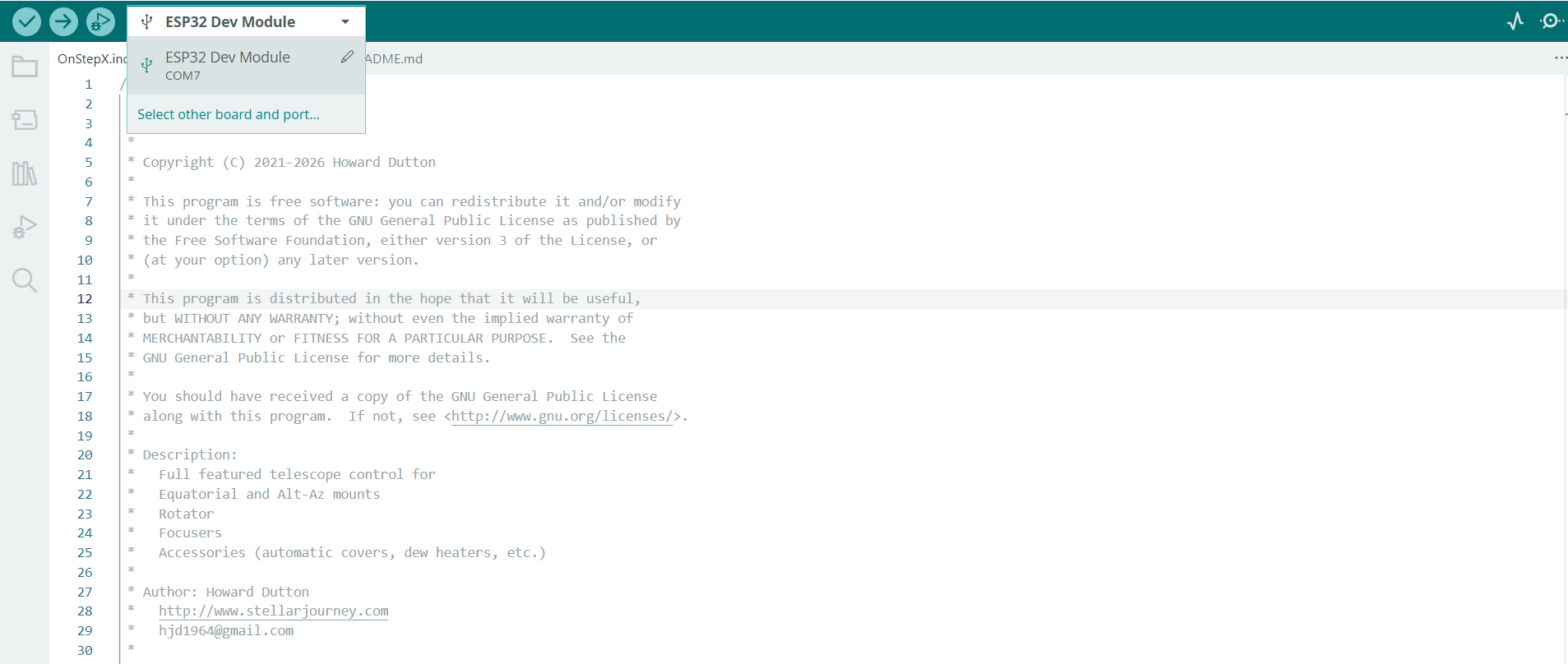
Select your ESP32 variant and the COM port it's connected to (in this build: ESP32 Dev Module on COM7).
Click Upload.
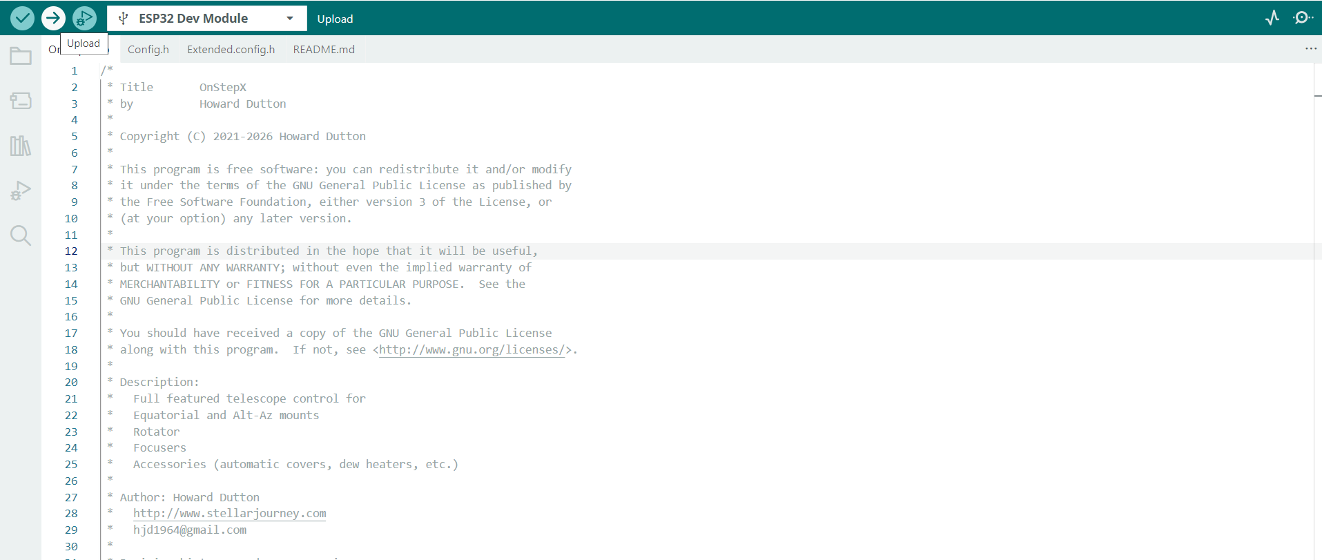
Verify the flash succeeded: open the Serial Monitor, type #GVP:, and press Enter. A response of Onstep confirms the firmware flashed correctly.
Once flashed, the ESP32 broadcasts its own Wi-Fi access point named OnStepX. Connect to it — the password is password.
Install OnStep Controller2 from the Play Store and open it.
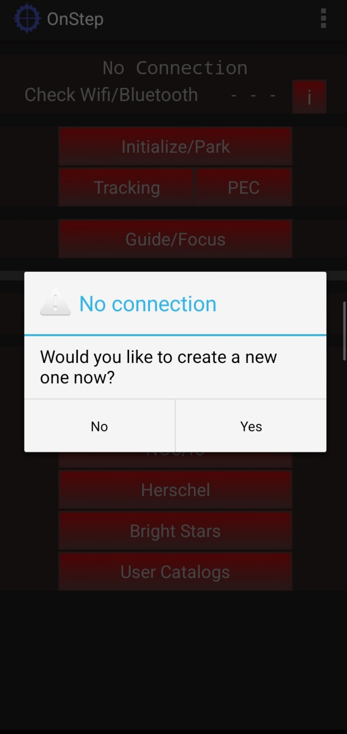
When prompted "Would you like to create a new one now?", tap Yes.
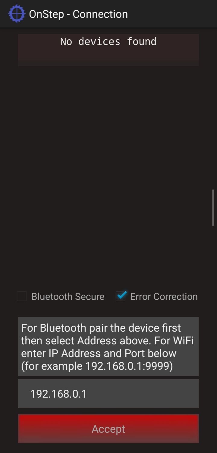
On the connection screen, enter the IP address 192.168.0.1 and tap Accept.
Wait a few seconds for the app to connect to the mount.
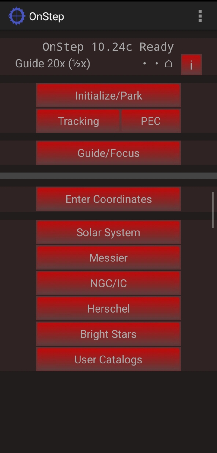
Tap the three-dot menu (top right) → Observing Sites, and enter your local Latitude, Longitude, and UTC Offset. Tap Upload, then return to the main menu.
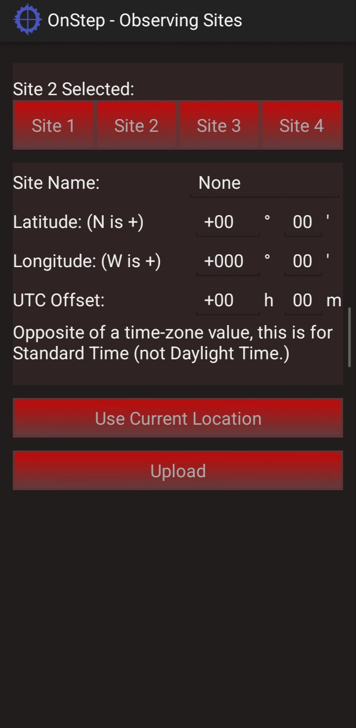
From the main menu, go to Initialize/Park. This is where most mount actions (park, unpark, home, goto) happen.
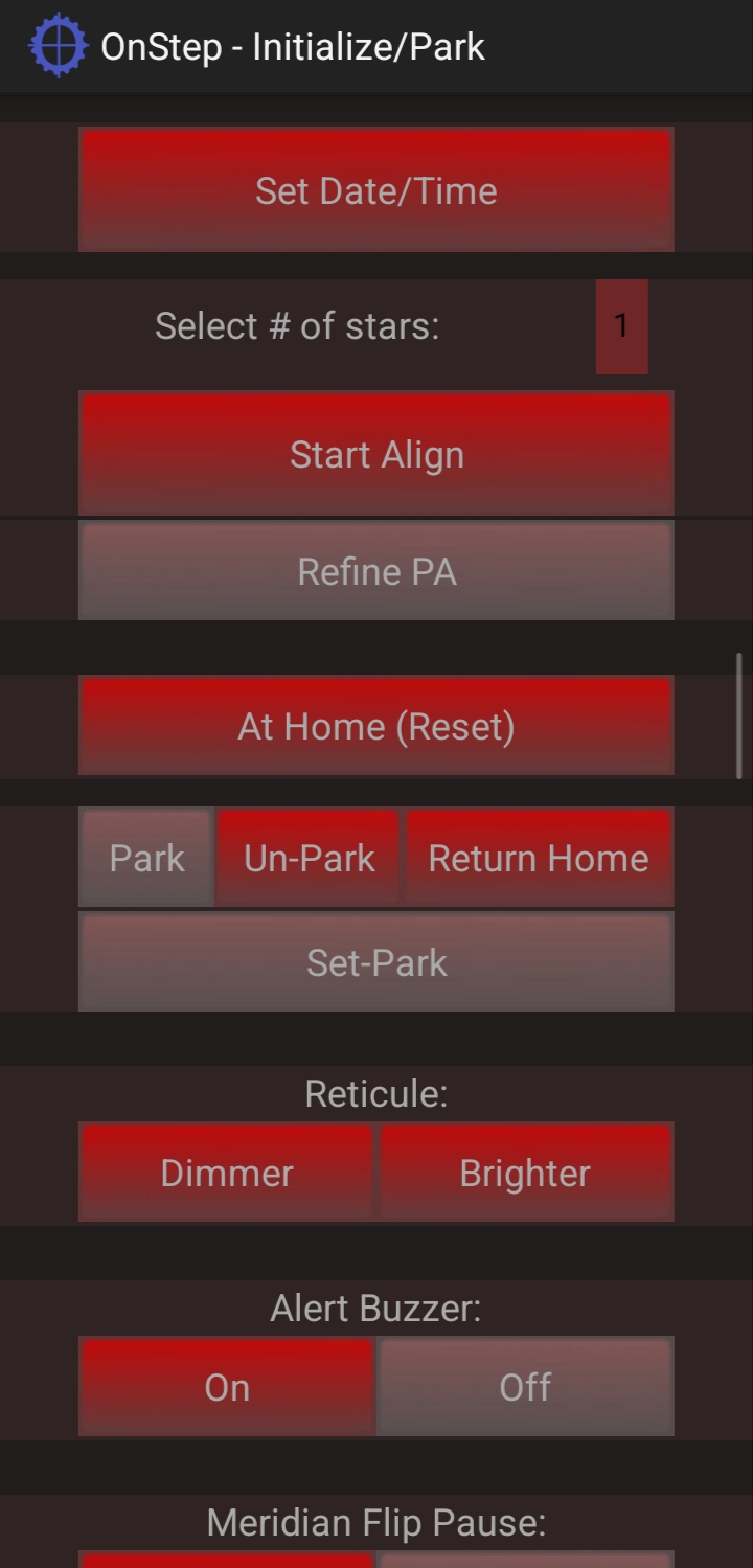
Important: Tap Set Date/Time before unparking. If this step is skipped, the mount won't accept any further commands.
Alternatively, the Triton GoTo App is worth trying — it includes a built-in planetarium view and has a more intuitive setup flow than the stock OnStep app.
A NEMA17 stepper motor takes 200 full steps per revolution (1.8° per step). Microstepping divides each full step into smaller increments for finer resolution:
| Driver | Max microsteps | Degrees per microstep | Steps per revolution |
|---|---|---|---|
| A4988 | 16 | 1.8° / 16 = 0.1125° | 3,200 |
| DRV8825 | 32 | 1.8° / 32 = 0.05625° | 6,400 |
Finer steps mean smoother, more precise tracking — important for accurately locating objects in the sky. This build started with an A4988 for initial testing, then upgraded to the DRV8825 for higher resolution (and for a second reason covered in Step 5).
Vref limits the current the driver delivers to the motor, protecting both the driver and the motor from damage.
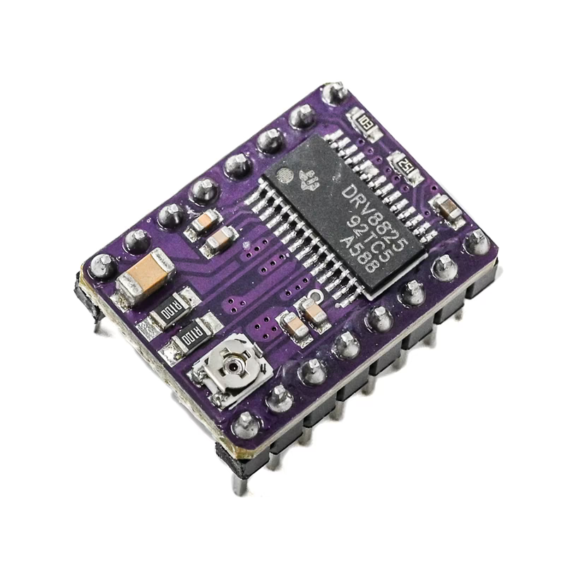
Vref is set using the small potentiometer on the driver board (turn carefully with a small screwdriver — it's easy to damage).
Formula:
Vref = Imax / 2For the NEMA17 motor used here, Imax = 1.2A per phase:
Vref = 1.2 / 2 = 0.6VFor a safety margin, this build used 10% less:
Vref = 0.5VTo measure and set it: power the driver with +5V (connect GND to GND, and FLT to +5V — the pinout may differ slightly by board, but this method works regardless). With the multimeter's red probe on the potentiometer and black probe on GND, adjust until the reading matches your target Vref.
If you run into trouble, this YouTube tutorial walks through the process on an A4988 — the same steps apply to the DRV8825. The main difference is that the DRV8825 has a FLT pin where the A4988 has VDD. See the DRV8825 connection notes for reference.
Identify motor coil pairs. On this motor, Red/Blue was Coil 1 and Green/Black was Coil 2 — verify yours with a multimeter or the tutorial linked above, since wire colors vary by motor.
Find your ESP32 pinmap. Inside the OnStepX folder, go to:
OnStepX > src > pinmaps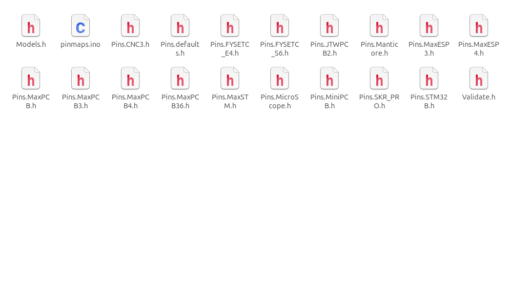
Select the file matching your MCU — this build used Pins.MaxESP3.h.
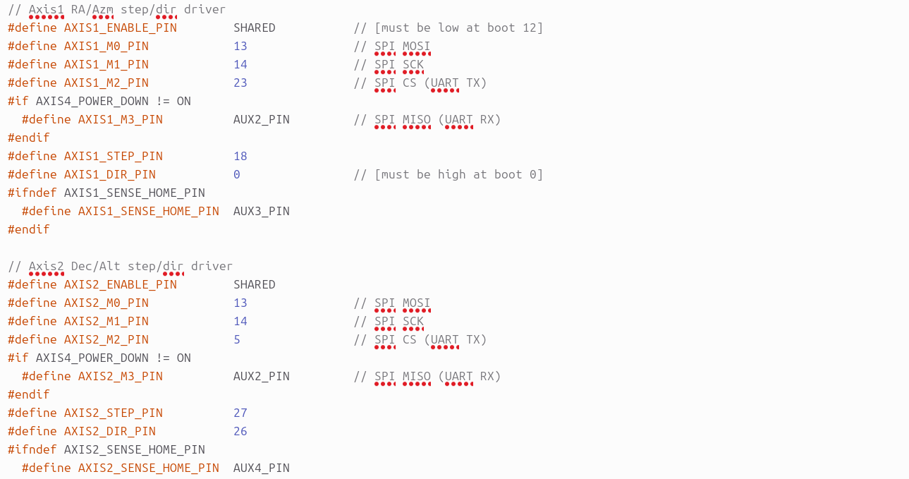
Scroll to the AXIS1 / AXIS2 definitions and wire accordingly. Optional buzzer/LED status pins can also be added here.
Wire the power stage. Connect the 100µF electrolytic capacitor as shown in the wiring video above. VMOT connects to +12V, and FLT connects to +5V — ideally from a step-down buck converter rather than the ESP32's own 5V rail.
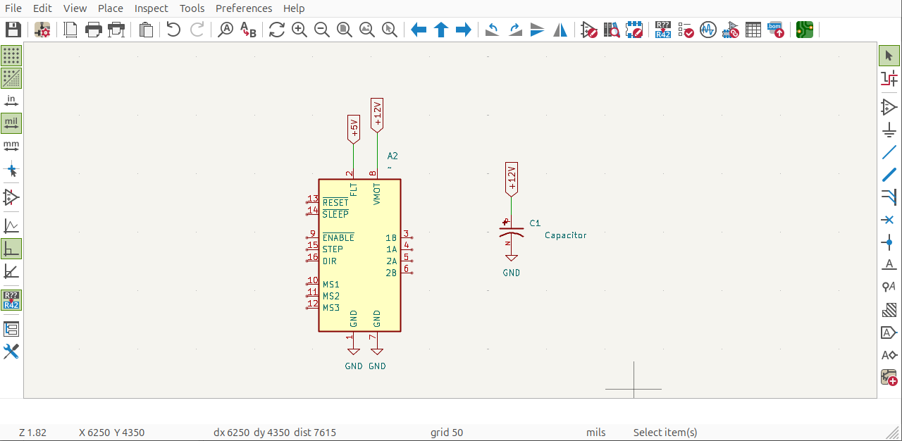
This build used a 12V, 2A supply.
Test one axis at a time. Wire and test Axis 1 (RA) first. Power on, connect the ESP32 via USB, open the OnStep app, and go to Guide/Focus to manually jog the motor and confirm it moves correctly in both directions.
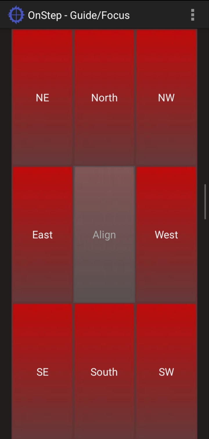
Once Axis 1 works, repeat the same wiring and test process for Axis 2 (Dec).
Run both axes together on the breadboard before moving to a permanent circuit.
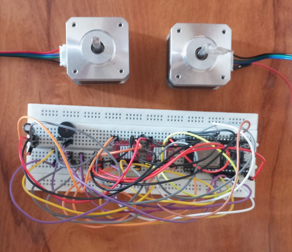
If motors behave erratically, check that the capacitor is installed and that the power supply is adequate. And if problems still persist there may be a fault with wiring itself.
The first PCB used for this build had an internal short at the 12V input hole, which cascaded into shorts across nearby resistors and capacitors — making the board unusable.
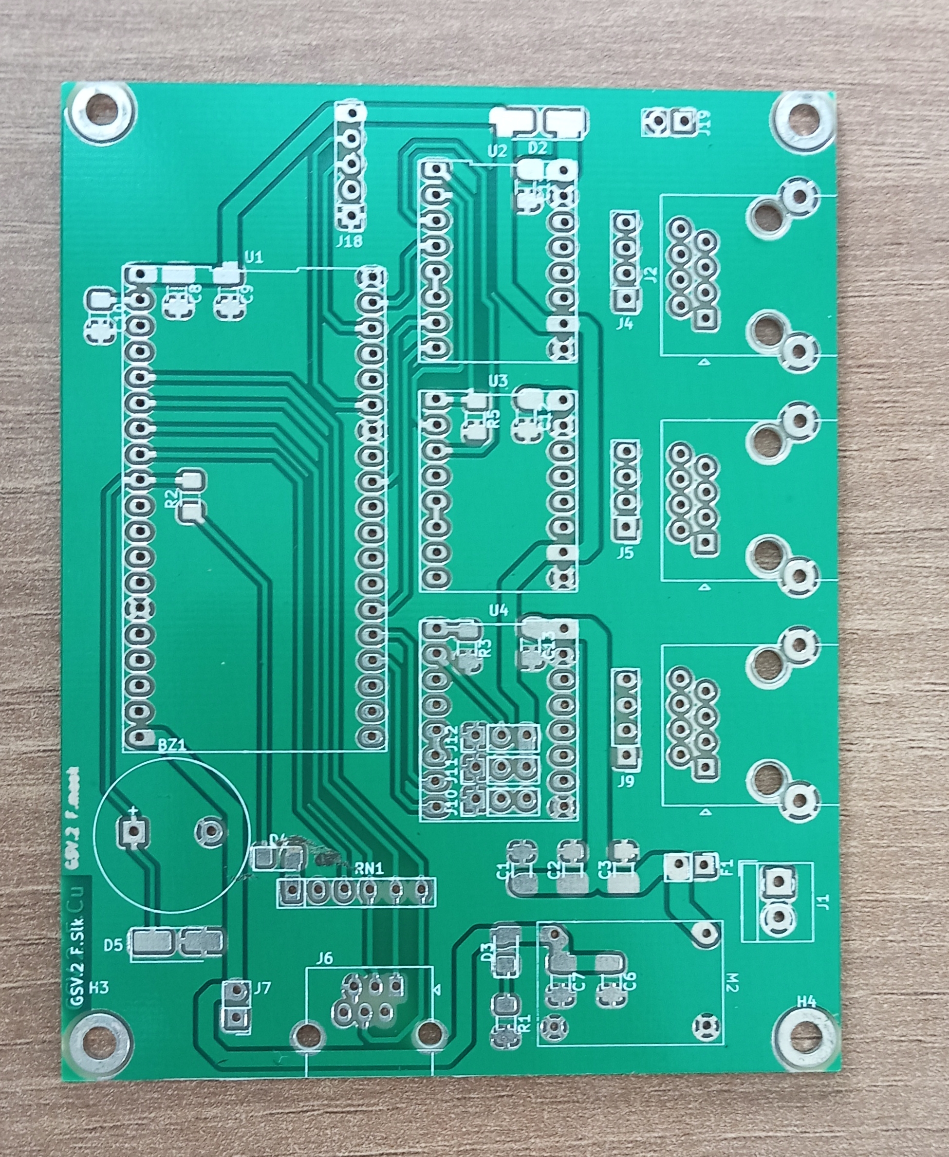
What is a short? A short circuit is an unintended low-resistance connection between two points (+12V and GND). This allows excessive current to flow, which can overheat and damage the circuit. A multimeter's continuity mode (which beeps when it detects a connection) is a fast way to check for shorts before powering anything on.
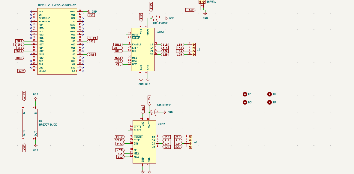
Since the original board was unrepairable, a custom PCB was designed from scratch in KiCad.
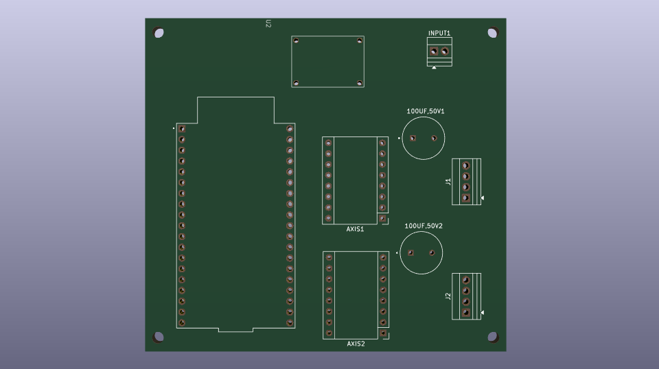
Schematic — includes the ESP32, A4988/DRV8825, and buck converter. Footprints for the ESP32 and driver were available online; the buck converter's footprint was custom-made by measuring the physical board.
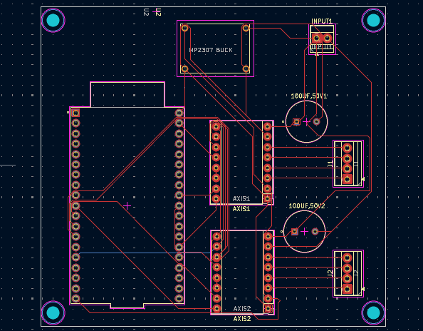
PCB layout — routed after the schematic was finalized.
3D preview — used to sanity-check the layout before fabrication.
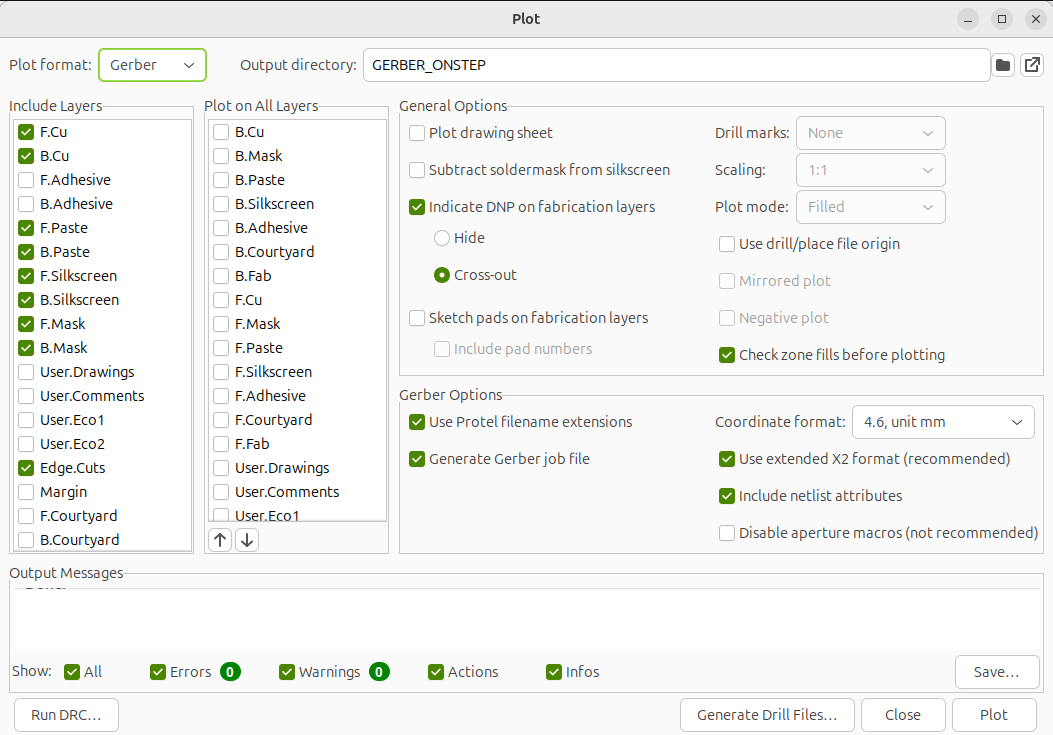
Generate Gerber files: File > Fabrication Outputs > Gerbers (.gbr). Run DRC first to catch errors, then Plot, then Save.
Fabrication and assembly:
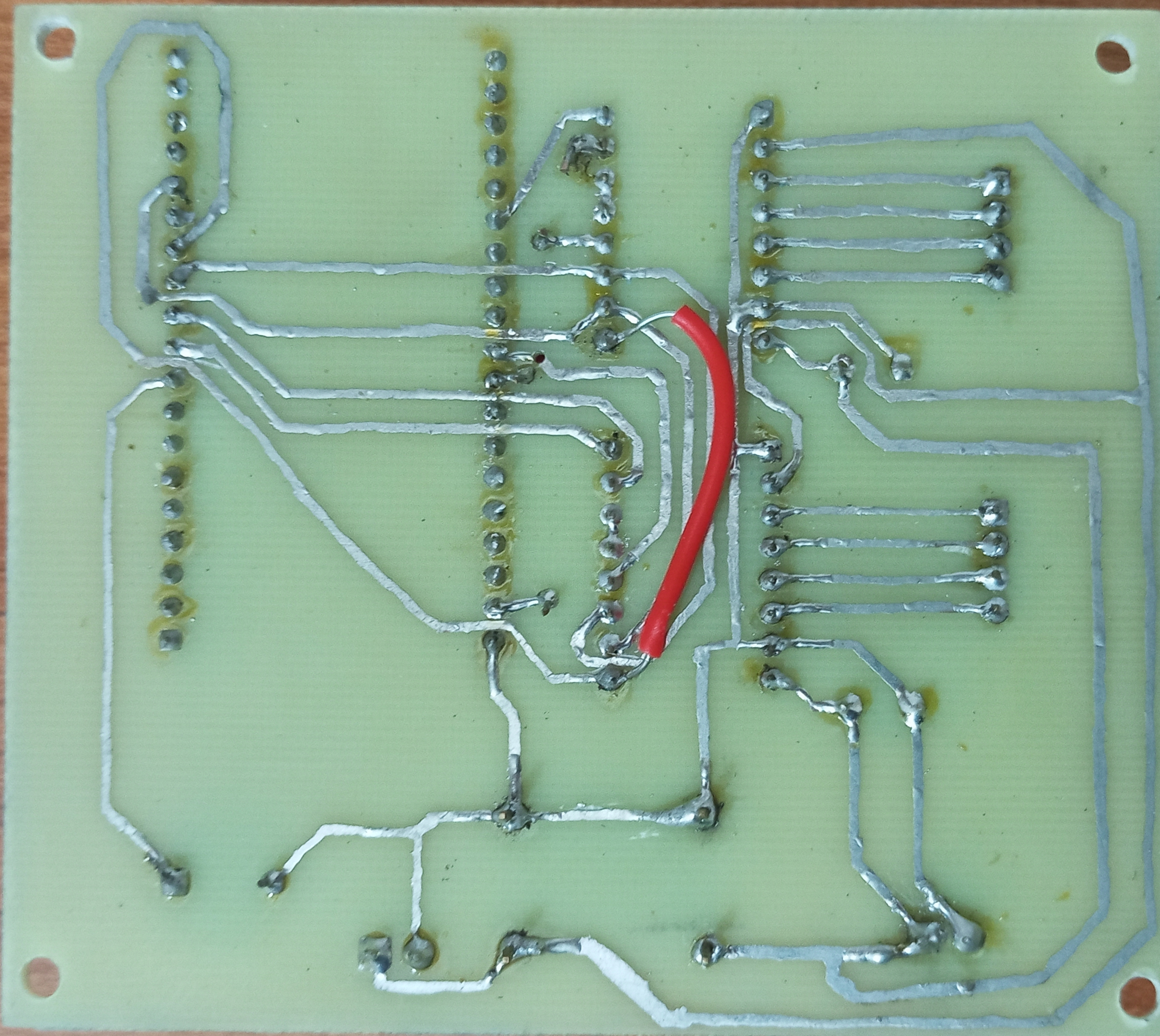
This is a single-sided PCB — the underside shows the routed copper tracks. Three connections that couldn't be routed on one layer were completed with single-strand jumper wire.
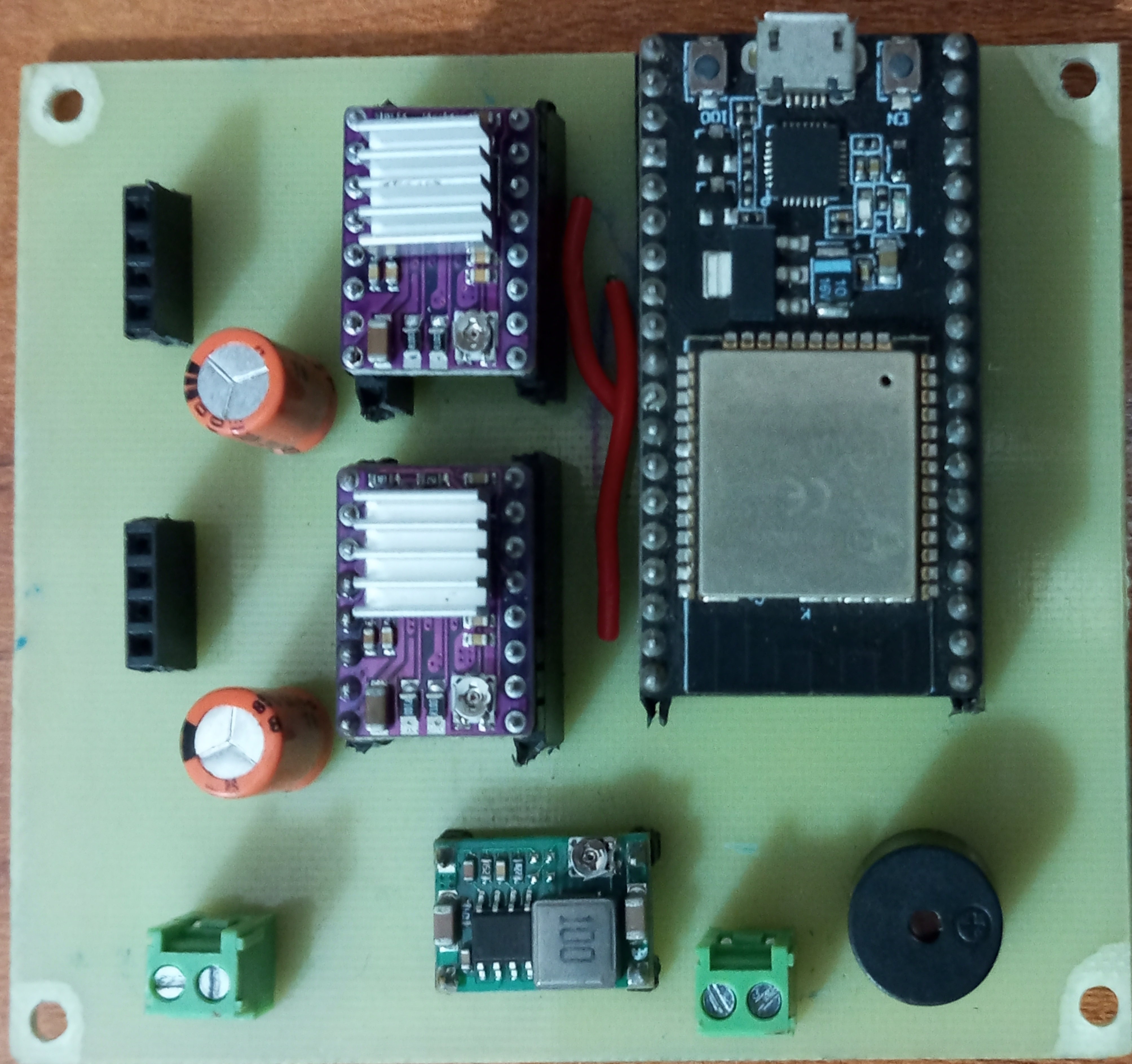
Populated components: ESP32, DRV8825, step-down buck converter, active buzzer, and the 100µF electrolytic capacitor. Motor and power connectors are separate.
Enclosure: a custom case was 3D-printed to house the finished board.
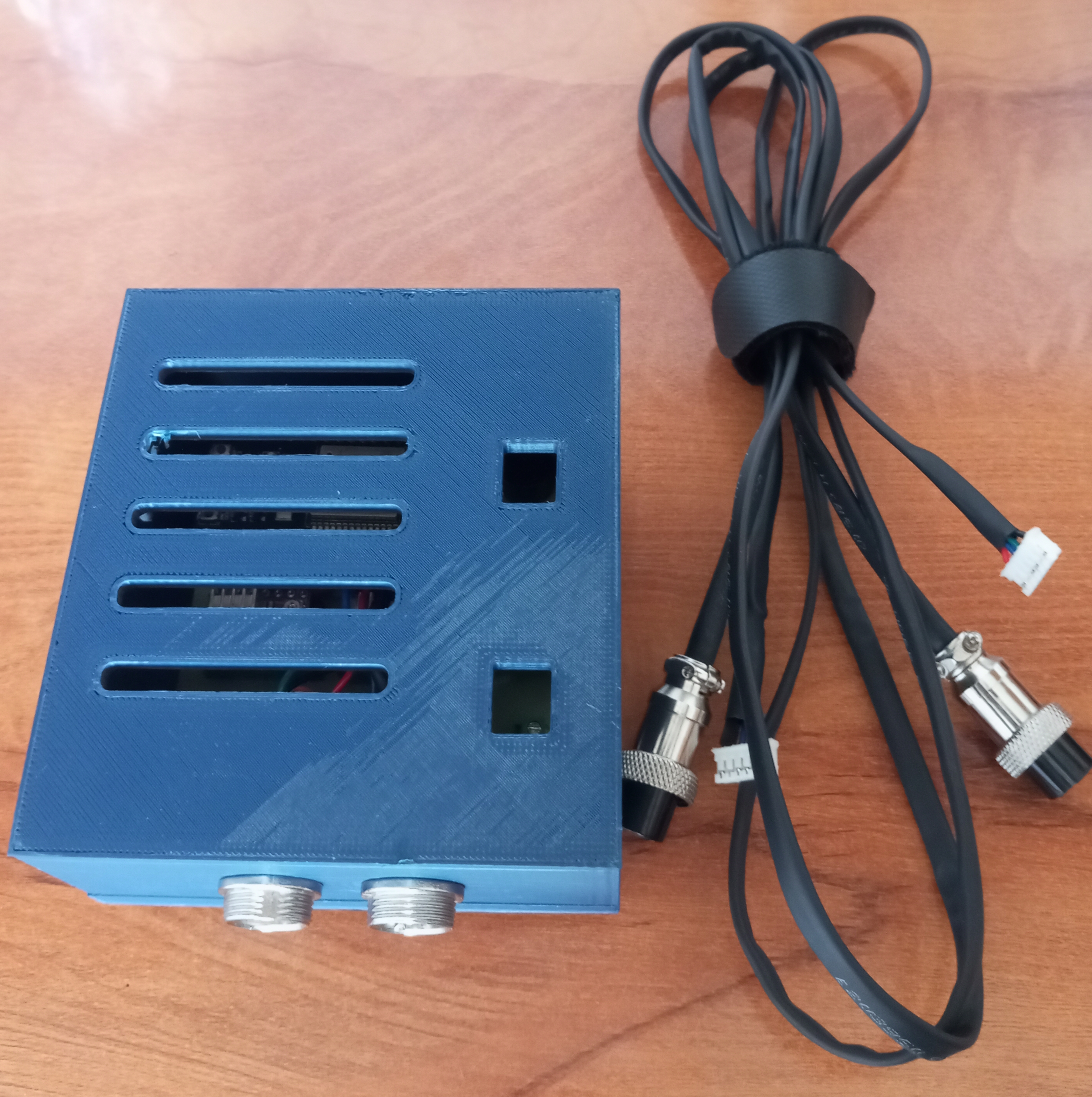
Motor driver connections to the NEMA17 use the motor's original connectors, soldered to 1-meter aviation connectors — long enough to avoid tension or interference around the mount.
This is the step that matches the firmware's electrical and mechanical parameters to your specific hardware — arguably as important as the wiring itself.
Go to the OnStep Configuration Generator.
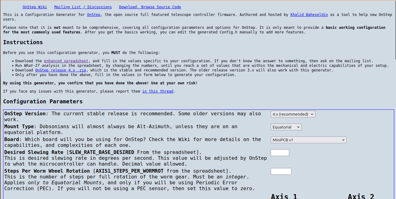 Credits: Khalid Baheyeldin
Download the enhanced spreadsheet it links to.
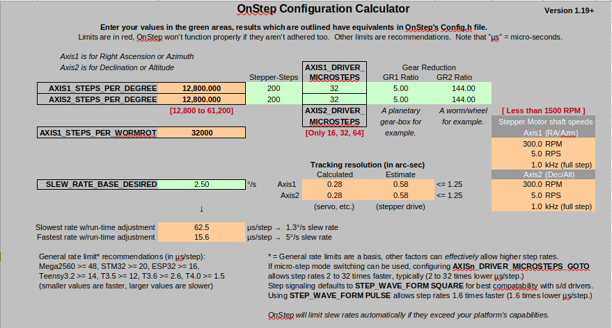
This spreadsheet calculates the correct settings for your driver and gearing. Key fields:
| Field | What it means | Value used in this build |
|---|---|---|
| Stepper Steps | Full steps per motor revolution (check your motor's datasheet) | 200 (NEMA17) |
| AXIS1/2_DRIVER_MICROSTEPS | Maximum microsteps your driver supports | 32 (DRV8825) |
| GR2 Ratio | Number of teeth on the mount's worm wheel | 144 (EQ4) |
| GR1 Ratio | Pulley gear ratio (large pulley teeth ÷ small pulley teeth) | 5 (60T / 12T) |
Checking if your gear ratio is sufficient:
Steps per degree = (Stepper Steps × Microsteps × GR1 × GR2) / 360With a DRV8825 (32 microsteps) and GR1 = 5:
(200 × 32 × 5 × 144) / 360 = 12,800 steps/degreeWith an A4988 (16 microsteps), a higher GR1 (≥10) is needed to hit a comparable resolution:
(200 × 16 × 10 × 144) / 360 = 12,800 steps/degreeHigher steps-per-degree means finer, more precise tracking resolution. Choose your driver's microstep setting and GR1 ratio together based on the resolution you need.
Fill in only the fields relevant to your hardware in the spreadsheet, leaving the rest at default, then return to the generator site and click Generate. This produces a Config.h file — copy it into your OnStepX folder (where the .ino file lives), replacing the existing Config.h when prompted.
OnStepX supports an optional web-based control interface via a plugin.
Download the plugin from the OnStepX-Plugins repository.
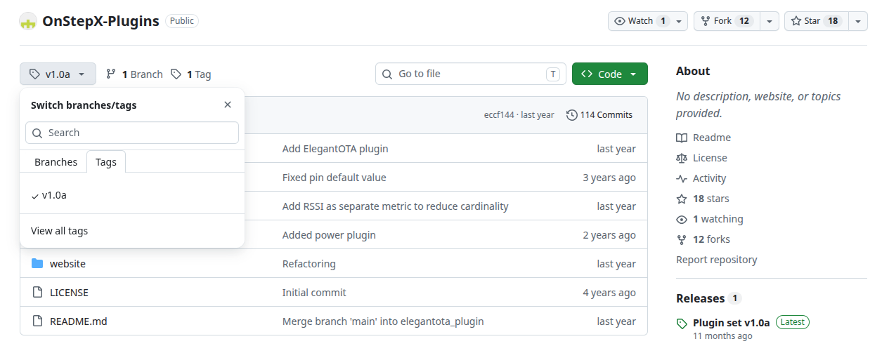 Credits: hjd1964
This build uses tag v1.0a specifically — the
mainbranch had errors at the time of writing.
Extract the download and copy the website folder into:
OnStepX > src > pluginsOpen Plugins.config.h and add:
#define PLUGIN1 website
#include "website/Website.h"
In Config.h, just below the PINMAPS section under SERIAL PORT COMMAND CHANNELS, add:
#define SERIAL_RADIO WIFI_ACCESS_POINTIn Extended.config.h, near the end of the file, add:
#define SERIAL_IP_MODE WIFI_ACCESS_POINT
#define WEB_SERVER on
Save both files and reflash the ESP32. Connect to its Wi-Fi network, then open a browser to 192.168.0.1 to reach the OnStepX web interface.
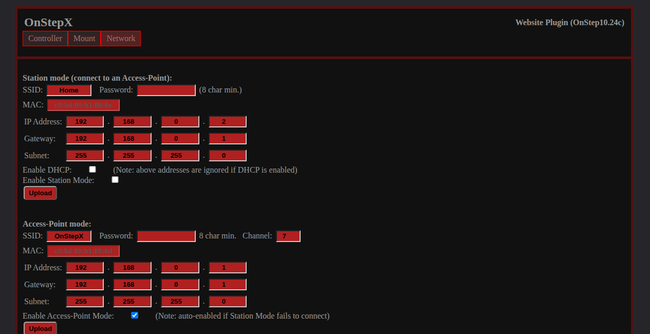
Web interface screens:
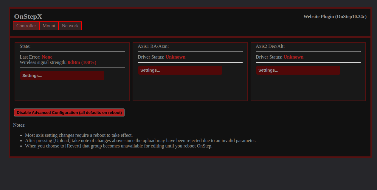
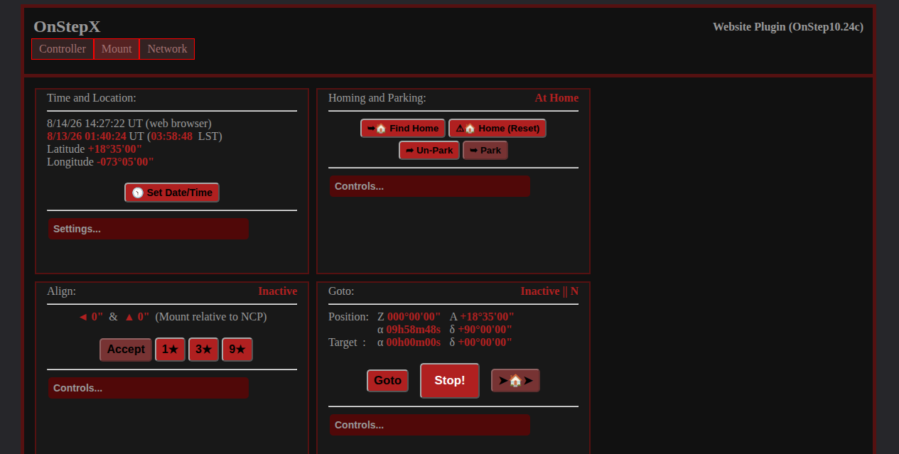
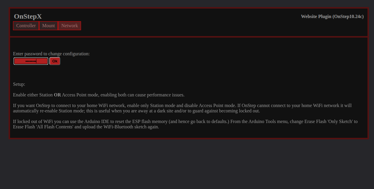
Opening the Network tab prompts for a password — again, it's password by default.
This build is based on a stock EQ4 mount.
Before adding any electronics, the mount was fully disassembled and inspected:
Some mounts — like the Explore Scientific EXOS2 with a OnStep kit — have screw holes purpose-built for motor brackets:
 Credits: Phobos Astronomy
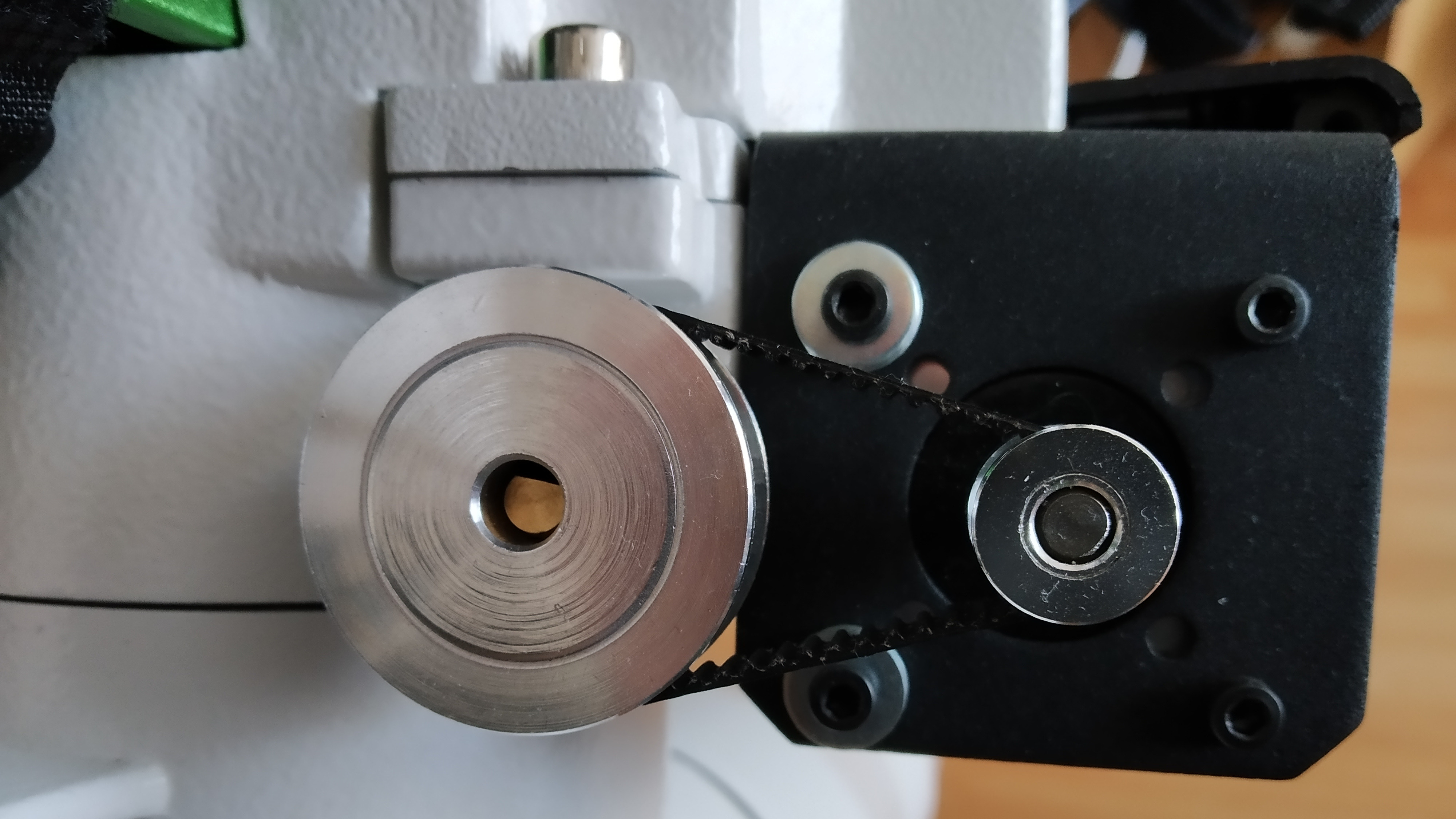
The EQ4 used in this build has no such mounting points, so brackets couldn't be bolted on directly. The workaround:
Per the Configuration step, this build uses a 5:1 gear ratio: a 60-tooth GT2 pulley on the worm shaft and a 12-tooth GT2 pulley on the motor. See the OnStep Drive Design wiki for guidance on choosing pulleys and belts for your own ratio.
An open-loop belt was tried first (cut to length and joined with super glue) since the correct closed-loop length wasn't known in advance — this didn't hold up, but it confirmed the needed belt length. A 180mm closed-loop GT2 belt was ordered afterward.
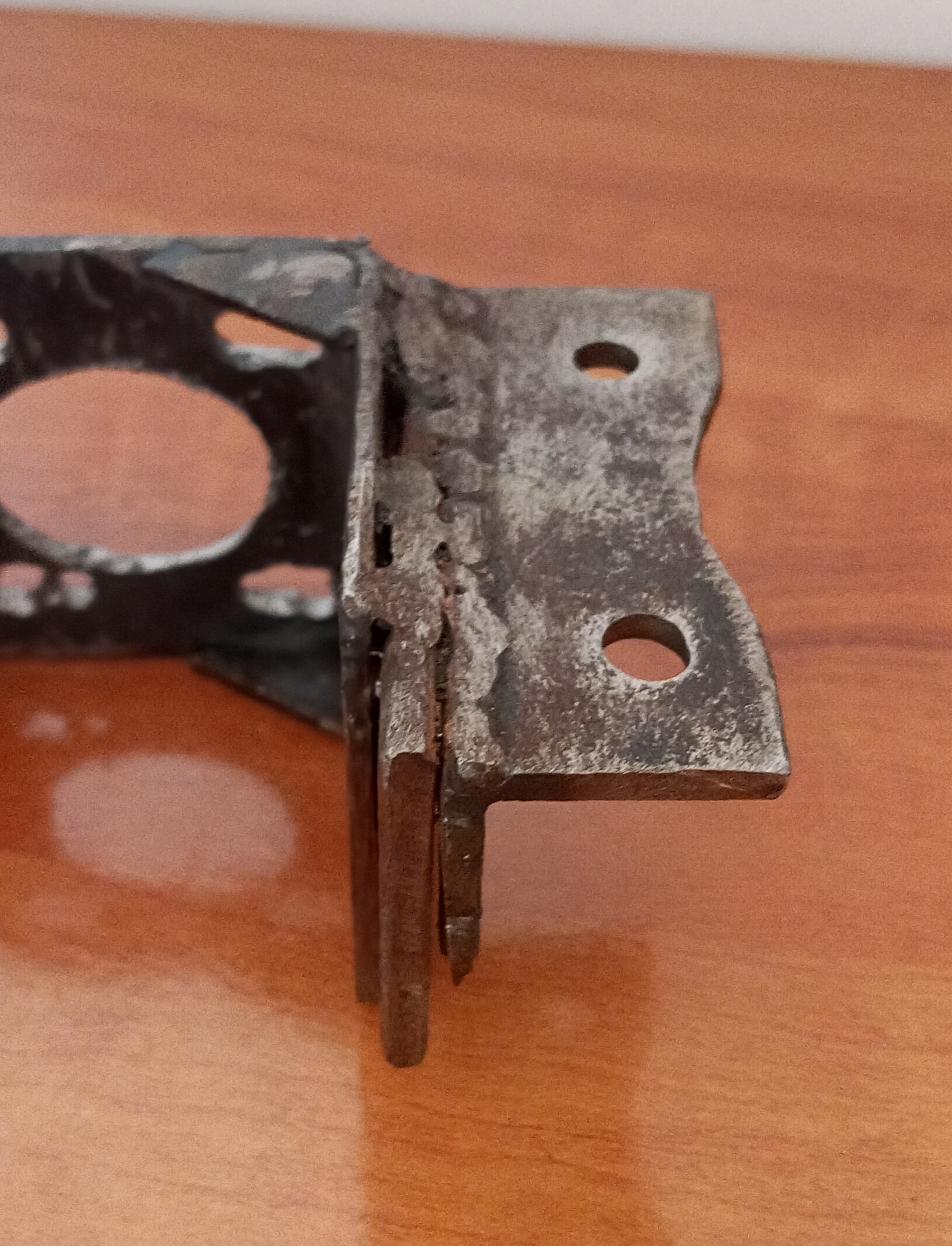
The belt ended up 4mm too long for the pulley spacing; a 4mm spacer plate was added between the steel angle and the bracket to compensate.
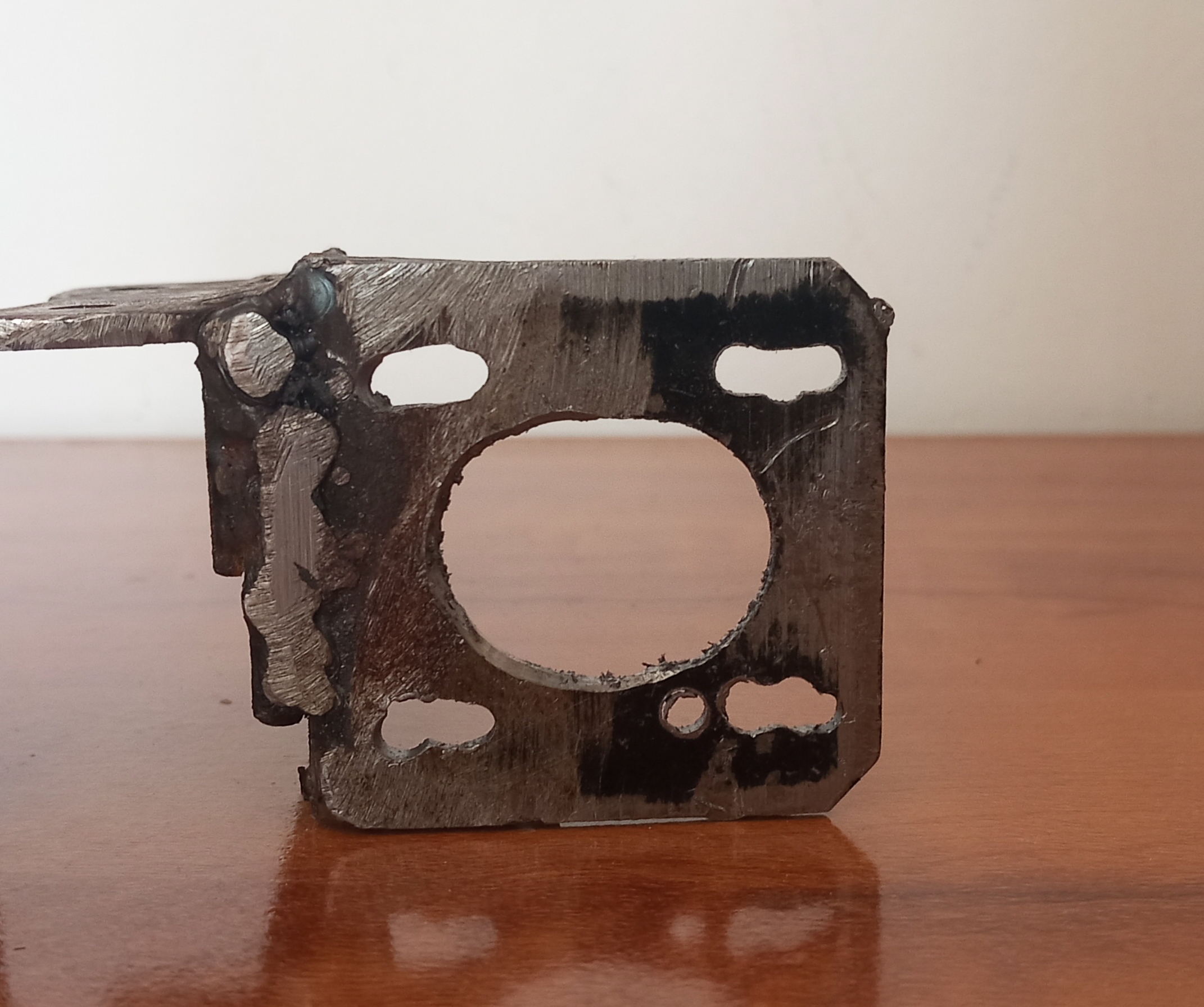
The bracket holes were also enlarged into oblong slots, allowing the motor to slide and adjust belt tension:
Final assembled Dec axis:
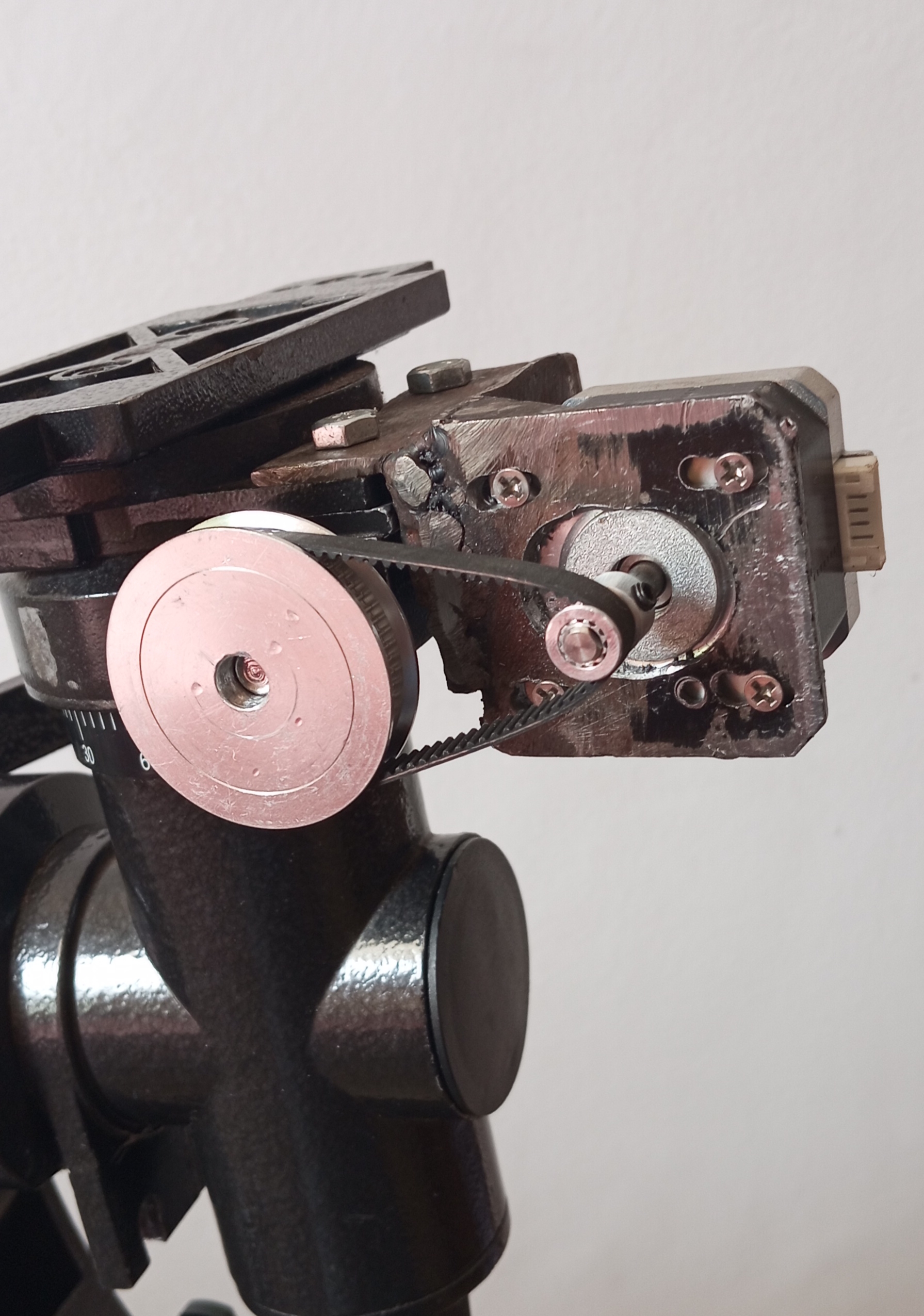
The same process was repeated for the RA axis.
More photos and testing videos (breadboard testing, PCB assembly, and mount tracking tests) are available here:
📁 **Google Drive — Photos & Videos
Both axes are wired, mechanically mounted, and configured. Remaining work / not yet documented here:
Hardware used in this build: EQ4 mount · ESP32 · DRV8825 · NEMA17 steppers · Custom KiCad PCB · OnStepX 10.24
This project uses v10.24 of OnStepX. All the changes mentioned above are present in files provided.
| Qty | Value | Footprint | References |
|---|---|---|---|
| 4 | MountingHole | MountingHole:MountingHole_2.7mm | H1, H2, H3, H4 |
| 2 | EEUFC1H101 | EEUFC1H101:CAPPRD500W60D1000H1250 | 100UF,50V1, 100UF,50V2 |
| 2 | Pololu_Breakout_A4988 | Module:Pololu_Breakout-16_15.2x20.3mm | AXIS1, AXIS2 |
| 2 | Screw_Terminal_01x04 | TerminalBlock:TerminalBlock_Xinya_XY308-2.54-4P_1x04_P2.54mm_Horizontal | J1, J2 |
| 1 | DEVKIT_V1_ESP32-WROOM-32 | DEVKIT_V1_ESP32-WROOM-32:MODULE_DEVKIT_V1_ESP32-WROOM-32 | U1 |
| 1 | MP2307 BUCK | MP2307:MP2307 Buck Converter | U2 |
| 1 | Screw_Terminal_01x02 | TerminalBlock:TerminalBlock_Xinya_XY308-2.54-2P_1x02_P2.54mm_Horizontal | INPUT1 |


samyk/magspoof
A portable device that can spoof/emulate any magnetic stripe, credit card or hotel card "wirelessly", even on standard magstripe (non-NFC/RFID) readers.

fossasia/pslab-scripts
Pocket Science Lab - Scripts for Sensor Experiments


willem-pennings/balancing-cube
A cube that balances itself in a corner or edge using reaction wheels

VoronDesign/Voron-Hardware
Cool Hardware designed by the Voron Design group

hoglet67/RGBtoHDMI
Bare-metal Raspberry Pi project that provides pixel-perfect sampling of Retro Computer RGB/YUV video and conversion to HDMI
It measures 90 × 78.5 mm and has 2 copper layers, 1.6 mm thick.
13 parts, built around the EEUFC1H101. The full list of its parts is on this page, with links to each part's symbol and footprint where PCBKit's library has them.
From the Cosmiccirkit01/OnStepX-Eq4 repository on GitHub, at the commit this page was made from: the board is KICAD/Layout/onstep.kicad_pcb and its schematic KICAD/Schematic/onstep.kicad_sch. PCBKit opens the board in the browser, with nothing to install.
Its repository publishes it under the GPL-3.0 licence: you may reuse it on that licence's terms (keep the author's notice, and for a copyleft licence share your changes alike).