

6 layers60 × 30 mm
Udsp card
crsknr/hw_udsp-card
A compact DSP development board for real-time embedded audio and sensing
221 parts2GPL-3.0

A serial console and power switching hat for the Raspberry Pi
Hat is an open-source printed circuit board by Cambridge-AdvancedOS, from the Cambridge-AdvancedOS/cam-power-uart-hat repository on GitHub. It is a 2-layer board of 56.3 × 20.3 mm with 40 parts on 29 nets, routed with 232 tracks and 21 vias.
It is built around the RQ5C060BCTCL. Its parts include 9 resistors, 6 diodes, 4 capacitors, 3 ICs and 3 connectors. It belongs with the interfaces and adapters boards of this library.
A Raspberry Pi Hat that provides USB serial access to the Pi's serial console. It allows for both power injection and switching via a JST-XH connector. There is also a combo temperature sensor/eeprom that can be accessed over USB.
Created for the L41 Advanced Operating Systems course at UCAM CST.
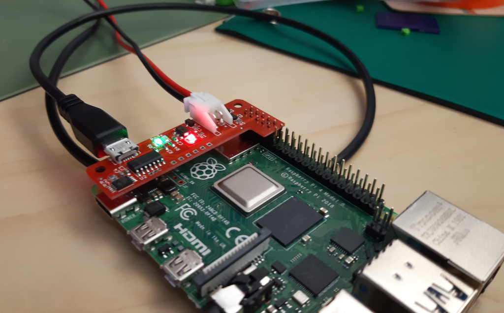
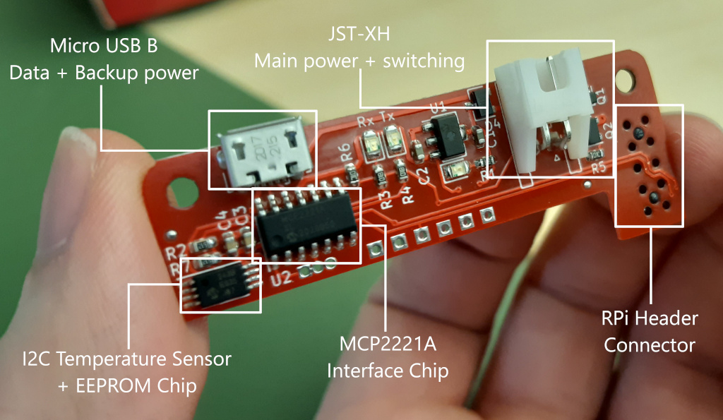
Designed by Thomas Bytheway for University of Cambridge.
Schematic details inspired by:
Designed by Limor Fried/Ladyada for Adafruit Industries.
Designed by Limor Fried/Ladyada for Adafruit Industries.
Creative Commons Attribution/Share-Alike, all text above must be included in any redistribution. See license.txt for additional details.
| Qty | Value | Footprint | References |
|---|---|---|---|
| 3 | 3k3 | Resistor_SMD:R_0603_1608Metric | R1, R8, R9 |
| 2 | 100n | Capacitor_SMD:C_0603_1608Metric | C3, C4 |
| 2 | 10k | Resistor_SMD:R_0603_1608Metric | R5, R6 |
| 2 | 1k | Resistor_SMD:R_0603_1608Metric | R3, R4 |
| 2 | 1u | Capacitor_SMD:C_0603_1608Metric | C1, C2 |
| 2 | 5k1 | Resistor_SMD:R_0603_1608Metric | R2, R7 |
| 2 | Fiducial | Fiducial:Fiducial_0.75mm_Mask1.5mm | FID1, FID2 |
| 2 | MountingHole | MountingHole:MountingHole_2.7mm_M2.5 | H1, H2 |
| 1 | 2N7002 | Package_TO_SOT_SMD:SOT-23 | Q1 |
| 1 | 3V3 | TestPoint:TestPoint_THTPad_1.5x1.5mm_Drill0.7mm | TP2 |
| 1 | 5V | TestPoint:TestPoint_THTPad_1.5x1.5mm_Drill0.7mm | TP1 |
| 1 | BUS | LED_SMD:LED_0805_2012Metric | D5 |
| 1 | CNN | LED_SMD:LED_0805_2012Metric | D1 |
| 1 | GND | TestPoint:TestPoint_THTPad_1.5x1.5mm_Drill0.7mm | TP6 |
| 1 | LOGO | pi-hat:bestie | G*** |
| 1 | LOGO | pi-hat:ucam | G*** |
| 1 | MCP1700T-3302E | Package_TO_SOT_SMD:SOT-89-3 | U1 |
| 1 | MCP2221AxSL | Package_SO:SOIC-14_3.9x8.7mm_P1.27mm | U2 |
| 1 | MCP98243-BE_ST | Package_SO:TSSOP-8_4.4x3mm_P0.65mm | IC1 |
| 1 | PI | LED_SMD:LED_0805_2012Metric | D6 |
| 1 | PWRON | TestPoint:TestPoint_THTPad_1.5x1.5mm_Drill0.7mm | TP3 |
| 1 | PWR_IN | Connector_JST:JST_XH_S2B-XH-A-1_1x02_P2.50mm_Horizontal | J1 |
| 1 | RB495DFH | Package_TO_SOT_SMD:SC-59 | D4 |
| 1 | RQ5C060BC | Package_TO_SOT_SMD:SOT-23 | Q2 |
| 1 | RST | Connector_PinHeader_1.27mm:PinHeader_1x03_P1.27mm_Vertical | JP1 |
| 1 | RX | TestPoint:TestPoint_THTPad_1.5x1.5mm_Drill0.7mm | TP5 |
| 1 | Raspberry_Pi_2_3 | Connector_Samtec_HLE_SMD:Samtec_HLE-105-02-xxx-DV-BE-A_2x05_P2.54mm_Horizontal | J3 |
| 1 | Rx | LED_SMD:LED_0805_2012Metric | D2 |
| 1 | TX | TestPoint:TestPoint_THTPad_1.5x1.5mm_Drill0.7mm | TP4 |
| 1 | Tx | LED_SMD:LED_0805_2012Metric | D3 |
| 1 | USB_B_Micro | Connector_USB:USB_Micro-B_Molex-105017-0001 | J2 |
crsknr/hw_udsp-card
A compact DSP development board for real-time embedded audio and sensing


hackclub/OnBoard
💡 Join 1,000 teenagers and make your first PCB with a $100 grant!

Chrismettal/EleLab_v2
Cheap DIY lab system for hobbyists and the tinkering folk

Chrismettal/flipper-zero-backpacks
Backpack-style addon boards for the Flipper Zero!


ohmtech-rdi/eurorack-blocks
Software to Hardware Prototyping for Eurorack using C++, Max/Gen~ or Faust
It measures 56.3 × 20.3 mm and has 2 copper layers, 1.6 mm thick.
40 parts, built around the RQ5C060BCTCL. The full list of its parts is on this page, with links to each part's symbol and footprint where PCBKit's library has them.
From the Cambridge-AdvancedOS/cam-power-uart-hat repository on GitHub, at the commit this page was made from: the board is board/hat.kicad_pcb. PCBKit opens the board in the browser, with nothing to install.
Its repository states no licence, so its author keeps all rights: ask Cambridge-AdvancedOS before reusing the design.