4 layers68 × 38 mm
Sensor Board
CMGeldenhuys/kleinvoet
Spatially-Distributed Temporally-Synchronised Infrasonic Recorder
67 parts3CERN-OHL-S-2.0

 CMGeldenhuys/kleinvoet3
Spatially-Distributed Temporally-Synchronised Infrasonic Recorder
Kleinvoet is an open-source printed circuit board by CMGeldenhuys, from the CMGeldenhuys/kleinvoet repository on GitHub, published under the CERN-OHL-S-2.0 licence. It is a 4-layer board of 122 × 66 mm with 189 parts on 155 nets, routed with 1,181 tracks and 548 vias.
It is built around the TPS73733QDRBRQ1, USBLC6-2SC6 and BLM15HD102SN1. Its parts include 74 capacitors, 48 resistors, 10 diodes, 9 connectors and 8 ICs. It belongs with the STM32 boards of this library.





Kleinvoet is a self-contained low-cost passive acoustic monitoring device. The recorder was initially designed for distributed infrasonic (8Hz) localisation, and features accurate temporal synchronisation through the use of an onboard GNSS module.
The recorder is capable of 24-bit stereo recording at a variable sampling rate of 8kHz to 192kHz. The recordings along with timestamp and operational log information is stored on a microSD card. The recordings are stored as a series of 256MiB WAV files.
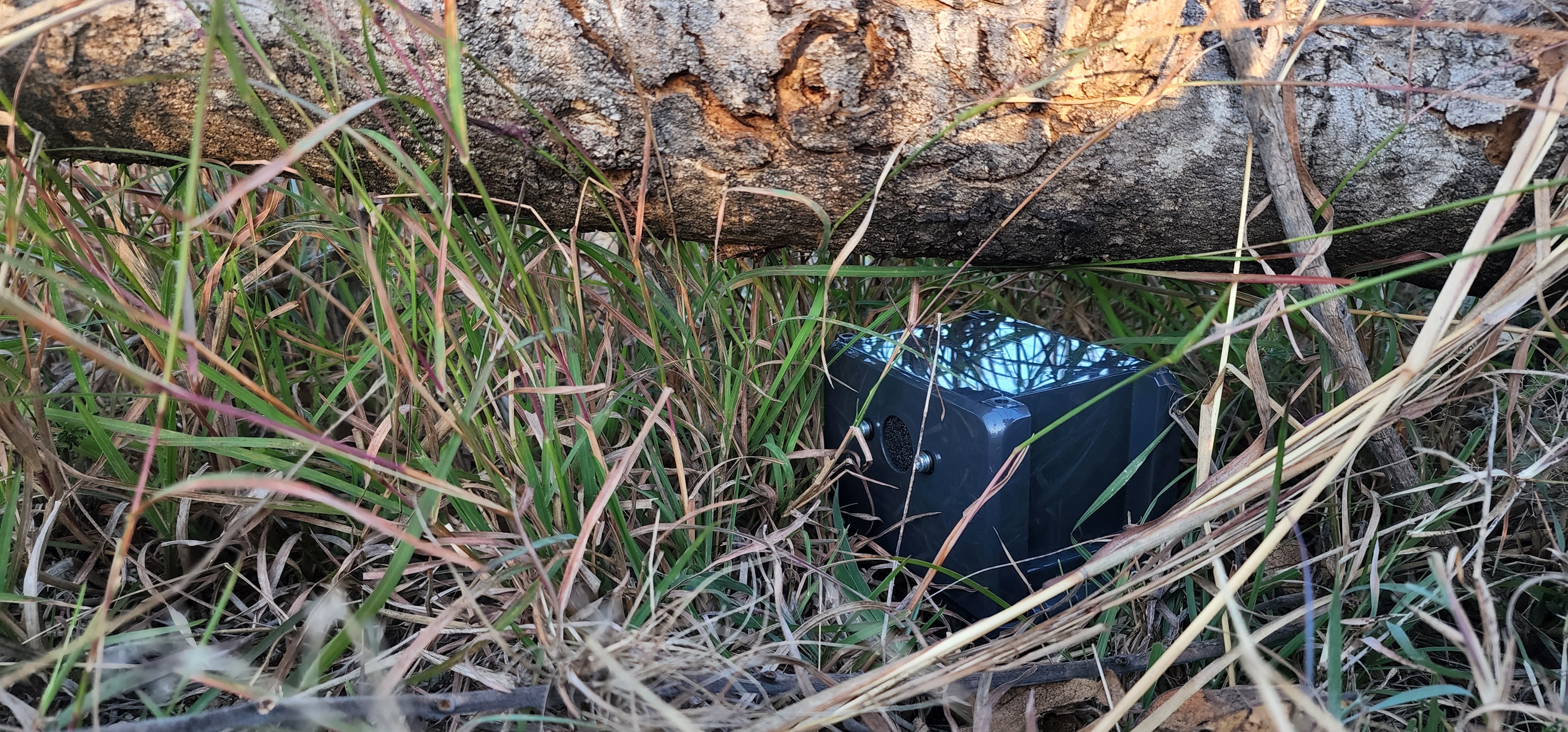
Firmware is available at CMGeldenhuys/kleinvoet-firmware.
All relevant production files such as panelised gerbers, bill of materials and work orders can be found in the production folder in the repo.
Additionally, the PCB layout and schematics for the Kleinvoet recorders can be found in the docs/pcb_single, docs/pcb_panel and docs/schematics directories, respectively.
In order to keep cost down, Kleinvoet does not make use of external SRAM. As such the I/O buffer is limited to the internal SRAM of the MCU. It is thus recommended using a class-10 high quality microSD card. Before a long-running experiment it is also recommended to do a "low-level" format of the microSD card. This will improve the write performance which is required at higher sampling rates.
To assemble a Kleinvoet node, one will require all the electronic components listed in the bill of materials (BOM), as well as have the necessary PCBs manufactured. The provided gerber files can be sent directly to most PCB fabrication houses. To assemble the boards, one can use either hot-air or plate reflow soldering methods. The interactive BOM might be useful when placing the components manually.
| PCB | Back | Front |
|---|---|---|
| Main Board | 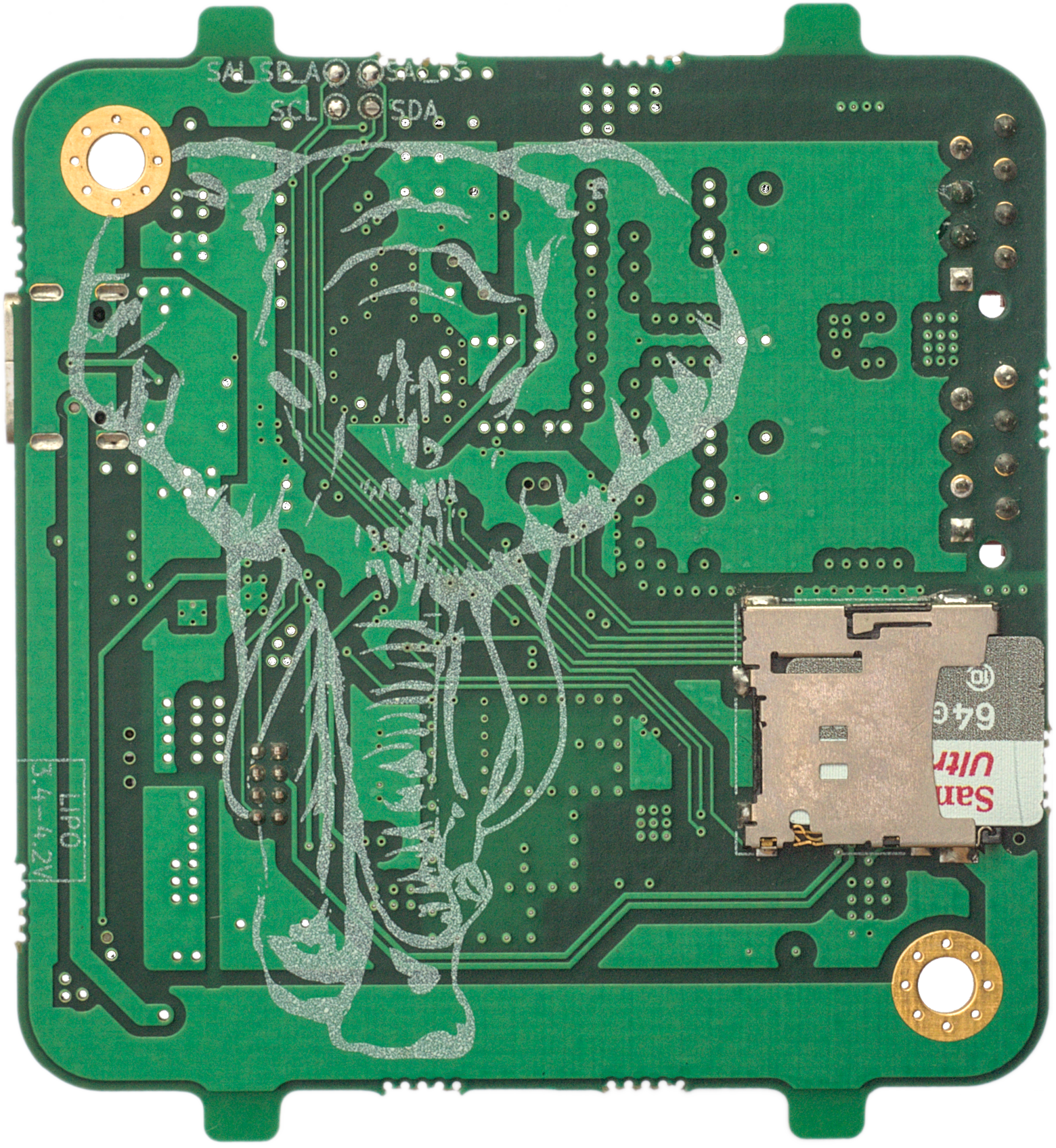 | 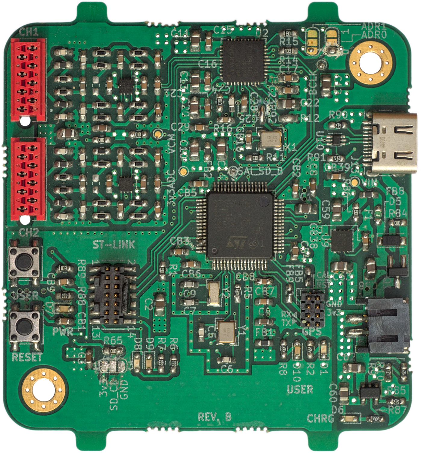 |
| GNSS Board | 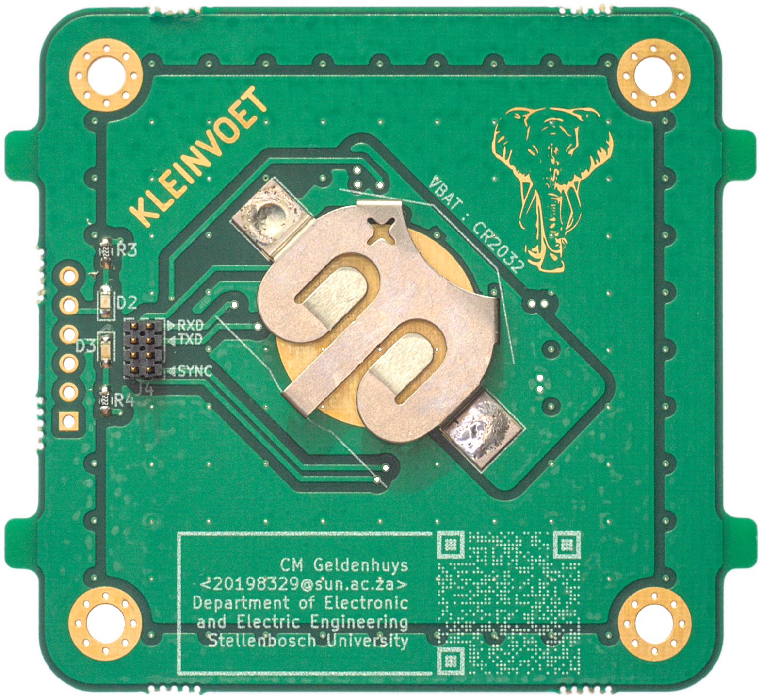 | 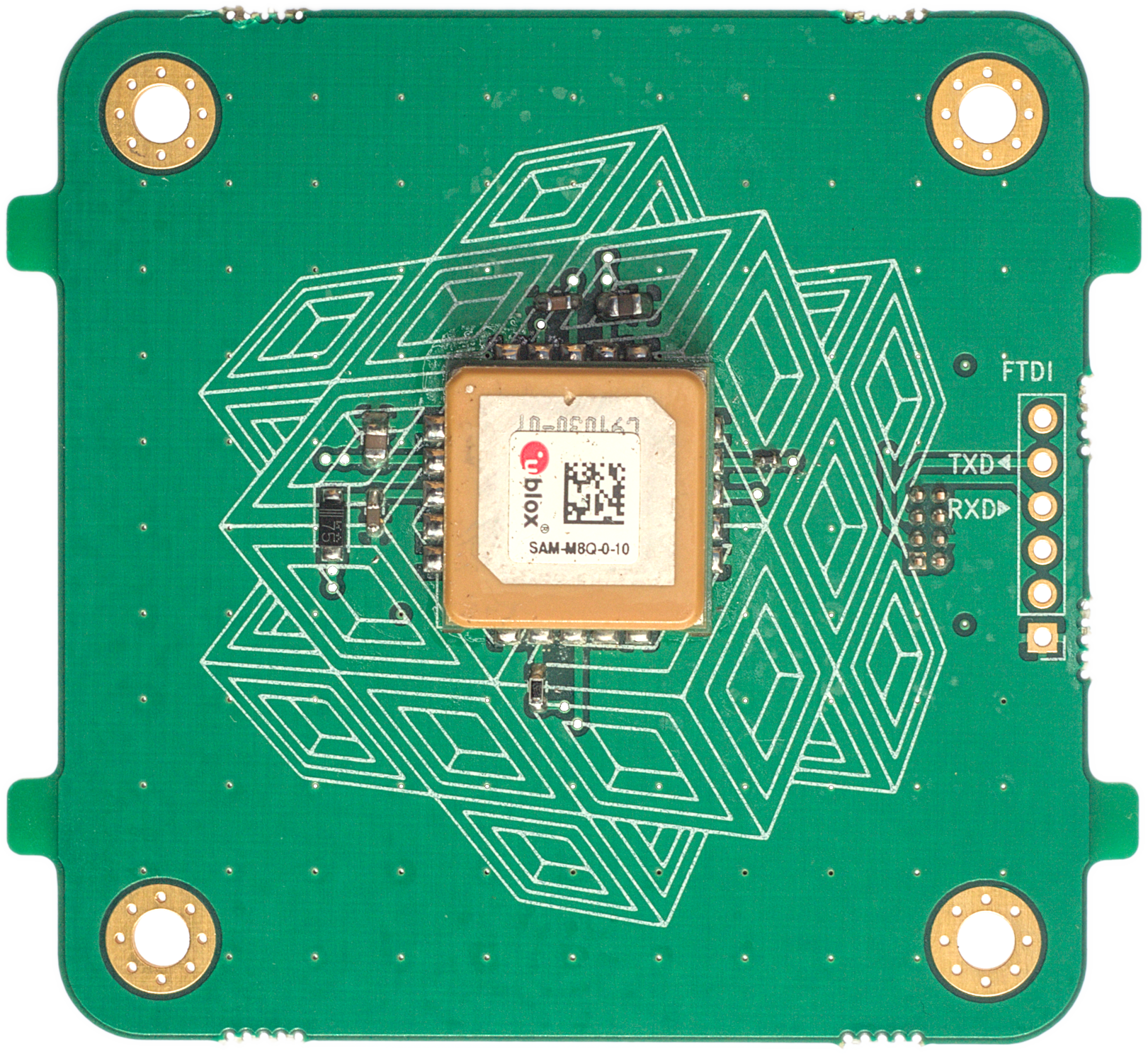 |
| Microphone Board | 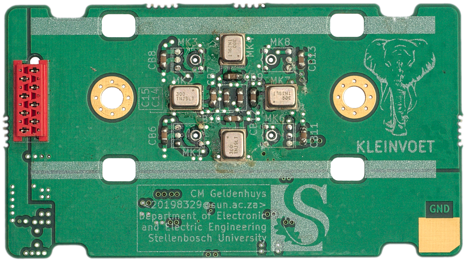 | 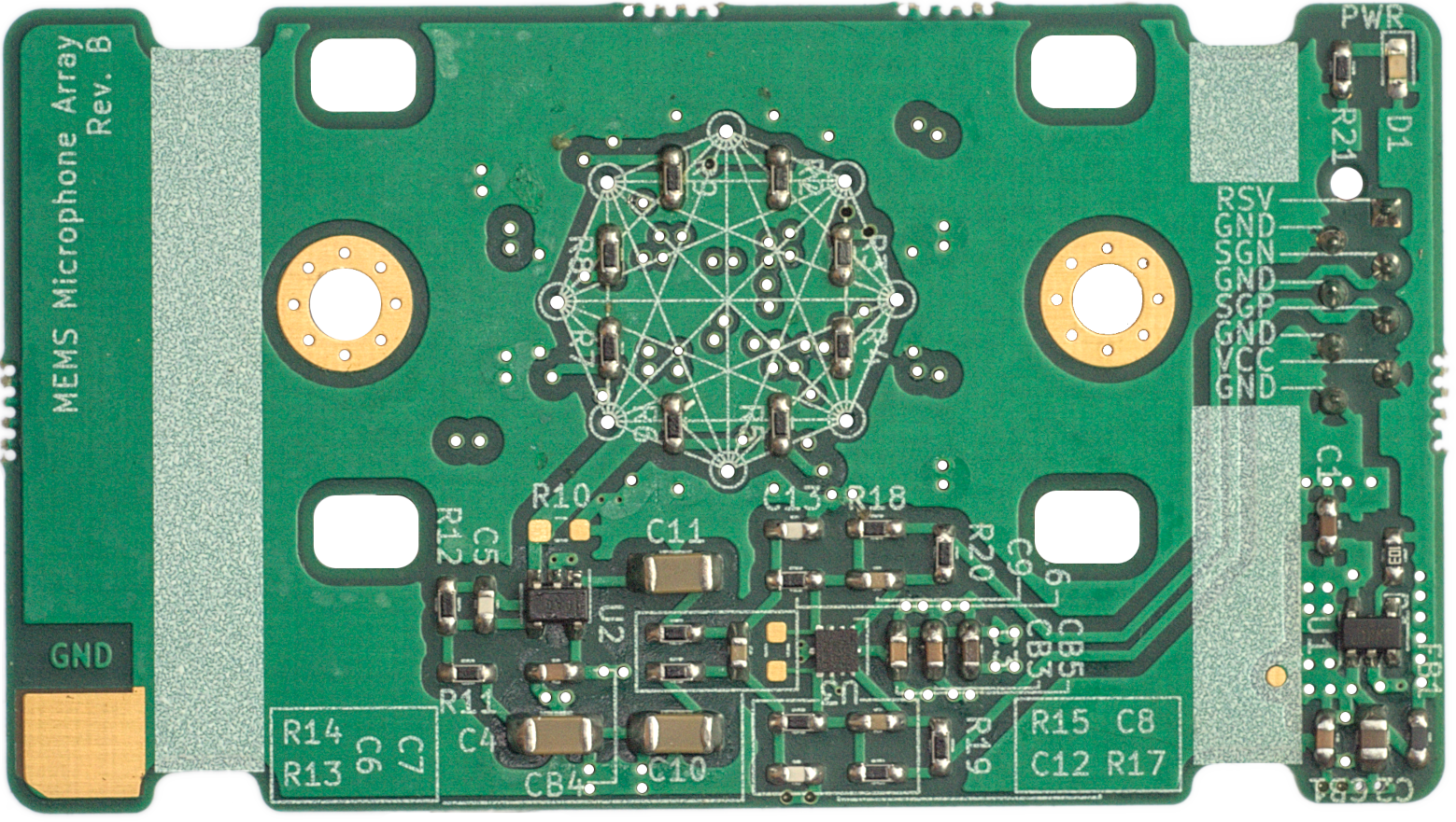 |
Once all the components have been soldered to their respective boards, the firmware can be flashed to the MCU using an ST Link debugger/programmer. However, not tested, any JTAG debugger/programmer should work. There are also open-source projects that use another STM32 MCU as a debugger/programmer (blackmagic probe).
Once programmed, proceed by connecting the GNSS header (marked on the respective PCBs) of the main board to the GNSS daughter board. Note, this connector can be reversed and the user should double-check that the SYNC pin (marked with an triangle) on the main board is connected to the SYNC pin of the GNSS board. If your use case does not require timestamping, the GNSS board can be omitted. Next, connect the microphone boards to their respective channels, marked on the main board's PCB as CH1 and CH2. These connectors are keyed, and thus It can only be connected one way.
If the user chooses to omit the weatherproof housing, Kleinvoet can be held together with two rubber bands. The notches on the main and GNSS boards snap together with the holes in the microphone boards to form a cube.
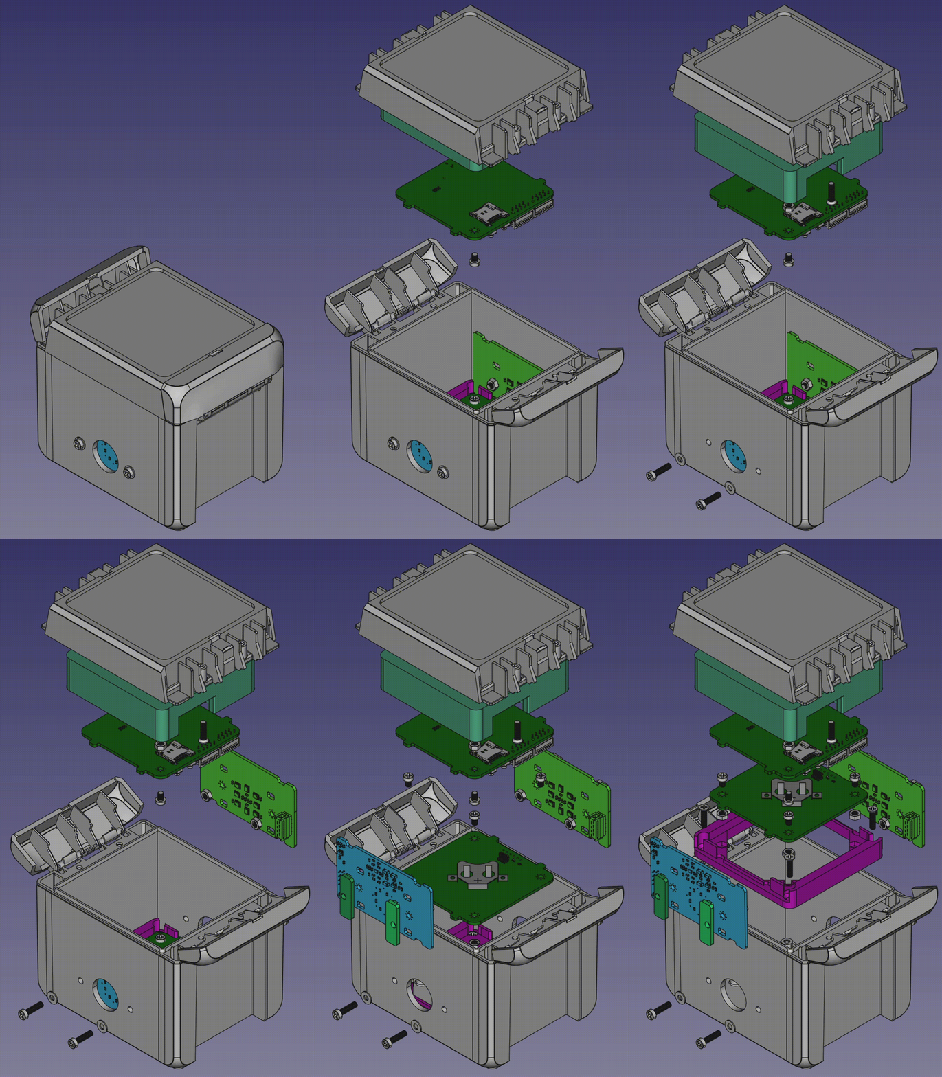
In order to assemble the weatherproof housing, start by placing the LiPo battery in the lid of the enclosure. Thread the battery lead through the hole of the main PCB adaptor plate. Next, mount the plate to the lid, keeping the battery in place. One can then proceed to mount the main PCB to the adaptor. Next mount the GNSS adaptor plate in the bottom of the Bocube housing, and mount the GNSS PCB to the adaptor. If using the windshielding, remove the backing paper and paste it firmly over the microphone inlets, (Note, the MEMS microphones used are bottom port microphone and thus the inlet port is on the bottom side of the PCB. The area to place the shielding foam is marked by a hashed circle) Install the microphone board spacers, ensuring that the mounting holes align properly. The microphone board assembly can now be mounted to the inside of the Bocube housing. Next, connect the individual daughter boards (GNSS and microphone PCBs) to their respective connectors on the main board.
Insert a FAT32 formatted microSD card into the main board and plug in the battery. The node will perform a self test, followed by a self configuration stage and then begin recordings. This process might take up to 10 seconds. Once the node is configured, a solid amber light will be illuminated. Please refer to the troubleshooting section if this is not the case.
Each PCB contains a RED status LED, used to indicate that the board has power. On the main PCB there are two running status indication LEDs (AMBER and BLUE).
When running, the AMBER LED will remain solid. Once a GNSS lock (both time and location) is obtained, the BLUE LED will pulse briefly every 10 seconds (default).
If an unrecoverable error has occurred, the two status LEDs (AMBER and BLUE), will pulse is quick succession. In this case, the watchdog timer will trigger and attempt to write the operational log and reset the device. During a catastrophic failure it might not be possible to write to the microSD card depending on the error that has occurred.
| State | Blue LED | Amber LED |
|---|---|---|
| Start-up | Blink (1s) | Off |
| Recording | Solid | X |
| GNSS Lock | X | Blink (10s) |
| Catastrophic Error | Strobe | Strobe |
In the table above, 'X' denotes a "do not care" or irrelevant status. In other words, it is not an indication of the current device state.
After recording, the following file structure will be present on the microSD card of the respective node.
(root)
├── REC_1
│   ├── KV.LOG
│   ├── REC.WAV
│   ├── REC.W01
│   ├── REC.W02
│   ├── REC.W03
│   └── TS.CSV
├── REC_X
│   ├── KV.LOG
│   ├── REC.WXX
│   └── TS.CSV
└── CONF.INI (experimental)
Each recording will be stored as a WAVE file in the corresponding REC_X
folder. Where the recorder increments X for every subsequent recording made on
the device (e.g. REC_1, REC_2 etc.). Inside each recording folder are the
files associated with that recording. Due to the limitation of the FAT32
filesystem each individual recording has to be split up across multiple WAVE
files (e.g.REC.WAV, REC.W01, etc.). By default, this is in 256 MiB chunks, but
is user configurable Contained in the header of each WAVE file is timestamping
and location information required to synchronise the nodes during offline
processing of the files. A granular log of the timestamping metadata is stored
in TS.CSV. A complete operational log is stored in KV.LOG, which might deem
useful in troubleshooting a faulty recording node. (Experimental) Currently the
node's configuration is compiled into the device firmware, however, there is a
experimental firmware branch that allows for the configuration to be stored on
the microSD.
| File/Folder | Purpose |
|---|---|
| REC_X | Folder containing all files associated with the particular recording |
| KV.LOG | Operational log of recordings |
| TS.CSV | Timestamping metadata |
| REC.WXX | Audio recording stored as a WAVE file |
| CONF.INI | (Experimental) Runtime configuration file |
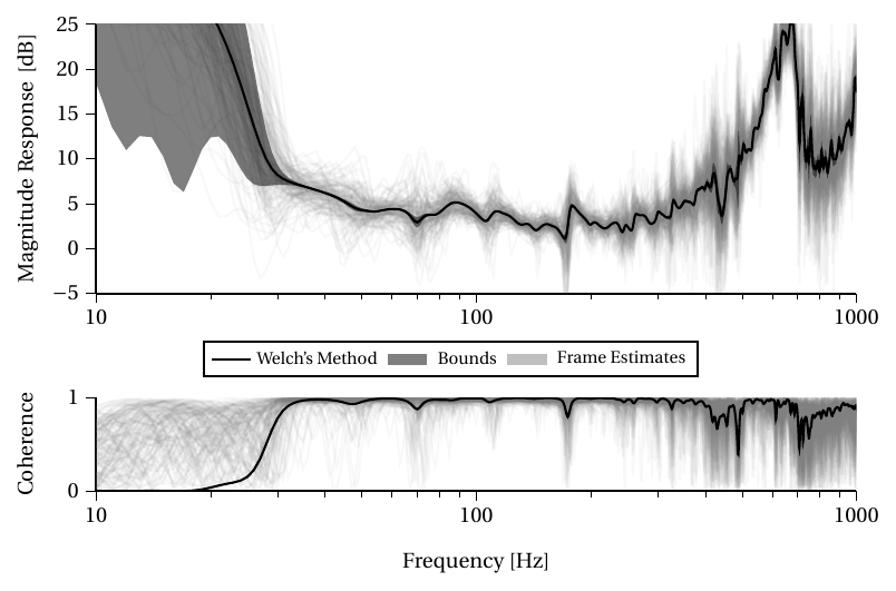
Provided below are a power spectral density estimates (PSD) generated using Welch's method. The Sennheiser MKH 8020 was used as a reference microphone and tested in an acoustically dampened recording studio. These results provide an estimate of the recording device's frequency response and should not be used as ground truth measurements where spectral magnitude accuracy is required. For those types of experiments, we recommenced the use of calibrated reference sound amplitude measurement equipment.
First ensure the following:
Enable LOG_DEST_TTY in config.h. The operational log will be printed in
real-time to the serial console available on the debug/programming port. When
using an ST Link debugger, this serial port can be opened using
Putty on Windows, or with the following command on
Linux:
screen -b 115200 /dev/ttyACM0The serial port is configured to 115200 baud rate and the standard 8N1 configuration. Please see the firmware guide for more information on setting up the programming environment on a Linux-based system.
We welcome contributions to the project. Unfortunately, hardware cannot be provided to contributors. However, the STM32 Nucleo-F446RE can be used as an firmware development alternative, and is readily available.
This project formed part of research done by the Electrical and Electronic Engineering Department at Stellenbosch University.

The Kleinvoet project is licensed under the CERN Open Hardware License version 2 (strongly-reciprocal variant). The license agreement and copyright only partain to the Kleinvoet recorder design. Third party CAD models and EDA footprints remain under the original license agreement and copyright of the respective intellectual property owners.
| Qty | Value | Footprint | References |
|---|---|---|---|
| 24 | 100n | Capacitor_SMD:C_0603_1608Metric_Pad1.08x0.95mm_HandSolder | C15, C16, C17, C21, C23, C28, C29, C37, C40, C43, C71, C74, C77, CB1, CB2, CB16 +8 |
| 17 | 10u | Capacitor_SMD:C_0805_2012Metric_Pad1.18x1.45mm_HandSolder | C1, C2, C10, C11, C12, C13, C14, C20, C22, C33, C58, C59, C60, C62, C63, C64 +1 |
| 8 | 2.2k | Resistor_SMD:R_0603_1608Metric_Pad0.98x0.95mm_HandSolder | R2, R3, R4, R6, R7, R8, R87, R88 |
| 8 | 220p | Capacitor_SMD:C_0603_1608Metric_Pad1.08x0.95mm_HandSolder | C18, C19, C26, C27, C30, C31, C61, C67 |
| 7 | 10k | Resistor_SMD:R_0603_1608Metric_Pad0.98x0.95mm_HandSolder | R1, R11, R12, R14, R15, R86, R89 |
| 6 | 10n | Capacitor_SMD:C_0603_1608Metric_Pad1.08x0.95mm_HandSolder | C42, C44, C76, C78, CB8, CB38 |
| 6 | 47 | Resistor_SMD:R_0603_1608Metric_Pad0.98x0.95mm_HandSolder | R20, R27, R28, R51, R52, R92 |
| 6 | MountingHole_Pad | MountingHole:MountingHole_3.2mm_M3_Pad_Via | H2, H3, H13, H14, H15, H16 |
| 5 | 1u | Capacitor_SMD:C_0603_1608Metric_Pad1.08x0.95mm_HandSolder | C3, C4, C8, C32, C66 |
| 4 | 100k | Resistor_SMD:R_0603_1608Metric_Pad0.98x0.95mm_HandSolder | R13, R19, R65, R84 |
| 4 | 15 | Resistor_SMD:R_0603_1608Metric_Pad0.98x0.95mm_HandSolder | R25, R26, R49, R50 |
| 4 | 3.9n | Capacitor_SMD:C_0603_1608Metric_Pad1.08x0.95mm_HandSolder | C38, C39, C72, C73 |
| 4 | 310 | Resistor_SMD:R_0603_1608Metric_Pad0.98x0.95mm_HandSolder | R17, R18, R41, R42 |
| 4 | 330 | Resistor_SMD:R_0603_1608Metric_Pad0.98x0.95mm_HandSolder | R21, R22, R45, R46 |
| 4 | 360 | Resistor_SMD:R_0603_1608Metric_Pad0.98x0.95mm_HandSolder | R23, R24, R47, R48 |
| 4 | Ferrite_Bead_Small | Inductor_SMD:L_0603_1608Metric_Pad1.05x0.95mm_HandSolder | FB3, FB4, FB7, FB11 |
| 3 | 5.1k | Resistor_SMD:R_0603_1608Metric_Pad0.98x0.95mm_HandSolder | R85, R90, R91 |
| 2 | 15pF | Capacitor_SMD:C_0603_1608Metric_Pad1.08x0.95mm_HandSolder | C5, C6 |
| 2 | 27n | Capacitor_SMD:C_0603_1608Metric_Pad1.08x0.95mm_HandSolder | C34, C68 |
| 2 | 4p | Capacitor_SMD:C_0603_1608Metric_Pad1.08x0.95mm_HandSolder | C7, C9 |
| 2 | 500k | Resistor_SMD:R_0603_1608Metric_Pad0.98x0.95mm_HandSolder | R9, R10 |
| 2 | BLM15HD102SN1 | Inductor_SMD:L_0603_1608Metric_Pad1.05x0.95mm_HandSolder | FB5, FB9 |
| 2 | BLM18KG101TZ1D | Inductor_SMD:L_0603_1608Metric_Pad1.05x0.95mm_HandSolder | FB1, FB2 |
| 2 | GPS_Transmission_Conn | Connector_PinHeader_1.27mm:PinHeader_2x04_P1.27mm_Vertical | J4, J16 |
| 2 | GREEN | LED_SMD:LED_0603_1608Metric_Pad1.05x0.95mm_HandSolder | D2, D8 |
| 2 | OPEN | Capacitor_SMD:C_0603_1608Metric_Pad1.08x0.95mm_HandSolder | C35, C69 |
| 2 | ORANGE | LED_SMD:LED_0603_1608Metric_Pad1.05x0.95mm_HandSolder | D6, D10 |
| 2 | Sensor_Conn | grootvoet:TE_7-215079-8 | J3, J6 |
| 2 | THS4551 | grootvoet:WQFN-10_RUN | U3, U5 |
| 2 | Vf low | Diode_SMD:D_SOD-123 | D4, D5 |
| 2 | YELLOW | LED_SMD:LED_0603_1608Metric_Pad1.05x0.95mm_HandSolder | D3, D9 |
| 1 | 100 @ 100 MHz | Inductor_SMD:L_0603_1608Metric_Pad1.05x0.95mm_HandSolder | FB8 |
| 1 | 12 MHz | grootvoet:ECS-33B | Y1 |
| 1 | 12.288MHz | grootvoet:ECS-TXO-3225MV | X1 |
| 1 | 1k | Resistor_SMD:R_0603_1608Metric_Pad0.98x0.95mm_HandSolder | R16 |
| 1 | 32.768 kHz | grootvoet:ECX-31B | Y2 |
| 1 | 390p | Capacitor_SMD:C_0603_1608Metric_Pad1.08x0.95mm_HandSolder | C25 |
| 1 | 400mA | Fuse:Fuse_0603_1608Metric_Pad1.05x0.95mm_HandSolder | F1 |
| 1 | 5.6n | Capacitor_SMD:C_0603_1608Metric_Pad1.08x0.95mm_HandSolder | C24 |
| 1 | 68 | Resistor_SMD:R_0603_1608Metric_Pad0.98x0.95mm_HandSolder | R5 |
| 1 | ADAU1978 | grootvoet:LFCSP-WQ-40-1EP_6x6mm_P0.5_CP-40-14 | U2 |
| 1 | ADDR0 | Jumper:SolderJumper-3_P1.3mm_Bridged12_RoundedPad1.0x1.5mm_NumberLabels | JP7 |
| 1 | ADDR1 | Jumper:SolderJumper-3_P1.3mm_Bridged12_RoundedPad1.0x1.5mm_NumberLabels | JP6 |
| 1 | BCLK | TestPoint:TestPoint_Pad_D1.0mm | TP6 |
| 1 | BLM15HD102SN1 | Inductor_SMD:L_0402_1005Metric | FB10 |
| 1 | BLUE | LED_SMD:LED_0603_1608Metric_Pad1.05x0.95mm_HandSolder | D1 |
| 1 | COIN_BAT | grootvoet:BatteryHolder_Keystone_3002_1x2032 | BT1 |
| 1 | Conn_ST_STDC14 | grootvoet:SAMTEC-FTSH-107-01-X-DV | J1 |
| 1 | FCLK | TestPoint:TestPoint_Pad_D1.0mm | TP7 |
| 1 | FTDI_Conn | Connector_PinHeader_2.54mm:PinHeader_1x06_P2.54mm_Vertical | J2 |
| 1 | JST-PH | grootvoet:JST_PH_S2B-PH-SM4-TB_1x02-1MP_P2.00mm_Horizontal | J12 |
| 1 | LOGO | grootvoet:Front_pattern | G*** |
| 1 | LOGO | grootvoet:Oliver_SilkScreen | G*** |
| 1 | LOGO | grootvoet:QR_Code | G*** |
| 1 | LOGO | grootvoet:Oliver_SolderMask_15x15mm | G*** |
| 1 | MCP73831-2-OT | Package_TO_SOT_SMD:SOT-23-5 | U8 |
| 1 | Micro_SD_Card_Det | grootvoet:microSD_HC_Molex_5031821852 | J11 |
| 1 | PMOS | Package_TO_SOT_SMD:SOT-23_Handsoldering | Q1 |
| 1 | RED | LED_SMD:LED_0603_1608Metric_Pad1.05x0.95mm_HandSolder | D7 |
| 1 | RESET | grootvoet:SW_SPST_PTS647 | SW1 |
| 1 | SCL | TestPoint:TestPoint_Pad_D1.0mm | TP11 |
| 1 | SD1 | TestPoint:TestPoint_Pad_D1.0mm | TP8 |
| 1 | SD2 | TestPoint:TestPoint_Pad_D1.0mm | TP9 |
| 1 | SDA | TestPoint:TestPoint_Pad_D1.0mm | TP10 |
| 1 | SD_DET_SEL | Jumper:SolderJumper-3_P1.3mm_Bridged12_RoundedPad1.0x1.5mm_NumberLabels | JP8 |
| 1 | STM32F446RETx | Package_QFP:LQFP-64_10x10mm_P0.5mm | U1 |
| 1 | TPS73733QDRBRQ1 | grootvoet:Texas_DRB0008A | U9 |
| 1 | TestPoint | TestPoint:TestPoint_Pad_D1.0mm | TP14 |
| 1 | USBLC6-2SC6 | grootvoet:SOT-666_Handsoldering | U10 |
| 1 | USB_C_Receptacle_USB2.0 | grootvoet:USB_C_Recepetacle_JAE_DX07S016JA1 | J13 |
| 1 | USER | grootvoet:SW_SPST_PTS647 | SW2 |
| 1 | VADC | TestPoint:TestPoint_Pad_D1.0mm | TP1 |
| 1 | VCM | TestPoint:TestPoint_Pad_D1.0mm | TP2 |
| 1 | ublox_SAM-M8Q | grootvoet:ublox_SAM-M8Q_HandSolder | U11 |
CMGeldenhuys/kleinvoet
Spatially-Distributed Temporally-Synchronised Infrasonic Recorder

FTHGL/GPS-PND
GPS Personal Navigation Device, STM32F301K6Ux, MS38SN3 gnss module, AZ1117-3.3

yagamy4680/drone-study
AUAV-OpenSource/FMUv4-PixRacer is the open hardware design of PixHawk FMUv4. It uses STM32F427 and MPU6000. (github)

peterpolidoro/mouse-joystick-pcb
KiCad design, fabrication package and documentation for a single-axis mouse joystick controller board: RP2040, TMC5130A stepper driver, brake and torque front ends, a pyControl UART peripheral for the Janelia Dudman lab…

aidanbrzezinski/test
. ├─ 3D # STEP 3D model export ├─ Images # Pictures and renders │ ├─ kibotresources # External resources for KiBot │ ├─ colors # Color theme for KiCad │ ├─ fonts # Fonts used in the project │ ├─ scripts # External…

janelia-kicad/tmc5160-usb
A stepper controller and driver board combining a TMC5160 and RP2040.

peterpolidoro/camera-gpio-interface-pcb
KiCad design and documentation for a passive interface board between three FLIR Blackfly S cameras, a pyControl breakout and a Neuropixels OneBox: screw-terminal camera connectors, BNC inputs and outputs, a 50-pin…


It measures 122 × 66 mm and has 4 copper layers, 1.6 mm thick.
189 parts, built around the TPS73733QDRBRQ1, USBLC6-2SC6 and BLM15HD102SN1. The full list of its parts is on this page, with links to each part's symbol and footprint where PCBKit's library has them.
From the CMGeldenhuys/kleinvoet repository on GitHub, at the commit this page was made from: the board is kleinvoet.kicad_pcb and its schematic ADC_Frontend.kicad_sch. PCBKit opens the board in the browser, with nothing to install.
Its repository publishes it under the CERN-OHL-S-2.0 licence: you may reuse it on that licence's terms (keep the author's notice, and for a copyleft licence share your changes alike).