2 layers68.6 × 53.3 mm
Nano2UNO Adapter-3V3
CMB27/Nano2UNO-Adapter-3V3
A circuit board to adapt 3.3V Arduino Nano boards the the Arduino UNO form factor.
17 partsCERN-OHL-P-2.0

 CMB27/Nano2UNO-Adapter-5V
A circuit board to adapt 5V Arduino Nano boards the the Arduino UNO form factor.
Nano2UNO Adapter-5V is an open-source printed circuit board by CMB27, from the CMB27/Nano2UNO-Adapter-5V repository on GitHub, published under the CERN-OHL-P-2.0 licence. It is a 2-layer board of 68.6 × 53.3 mm with 16 parts on 31 nets, routed with 151 tracks and 0 vias.
It is built around the PJ-102A, PPPC151LFBN-RC and TSW-103-15-L-D. Its parts include 8 connectors, 1 diode and 1 switch. It belongs with the interfaces and adapters boards and the AVR (ATmega, ATtiny) boards of this library.

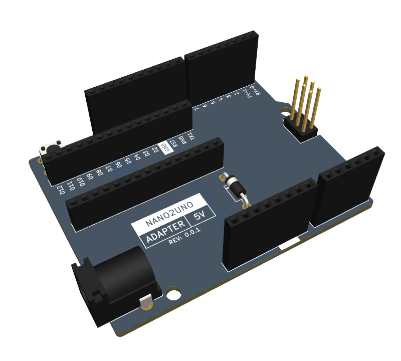
The Nano2UNO Adapter 5V is a circuit board to adapt 5V Arduino Nano boards the the Arduino UNO form factor.
All the IO pins on the Nano2UNO Adapter 5V are wired one to one from the Nano to the UNO form factor, no exceptions. Pins A6 and A7 of the Nano are not connected because these pins are not present in the UNO form factor.
[!NOTE] This design is distributed WITHOUT ANY EXPRESS OR IMPLIED WARRANTY, INCLUDING OF MERCHANTABILITY, SATISFACTORY QUALITY AND FITNESS FOR A PARTICULAR PURPOSE.
The Nano2UNO Adapter 5V should, in theory, be compatible with the following Arduino Nano boards:
Below are some circuit board manufacturers I have used in the past. Generally you will need to upload the upload the gerber and drill files to their websites in a .zip folder.
OSH Park is a US based circuit board fabrication service. They tend to be more expensive than other manufacturers and the number of options they give you are limited (If you use this manufacturer, I hope you like purple).
Seeed Studio Fusion makes circuit boards in China. They have a lot of options when ordering; please refer to the specifications above when making your choices. They do have a circuit board assembly service as well, but I am not especially familiar with it.
| References | Quantity | Manufacturer | Part Number | Description | Notes |
|---|---|---|---|---|---|
| D1 | 1 | Vishay | SB260S-E3/54 | DO-41 Diode | This provides reverse voltage protection on the VIN pin and barrel jack. |
| J1, J3 | 2 | Samtec | ESW-108-33-L-S | 1x8 Socket Header | These are extended socket headers that make up part of the Arduino UNO interface. |
| J2 | 1 | Samtec | ESW-110-33-L-S | 1x10 Socket Header | This is an extended socket header that makes up part of the Arduino UNO interface. |
| J4 | 1 | Samtec | ESW-106-33-L-S | 1x6 Socket Header | This is an extended socket header that makes up part of the Arduino UNO interface. |
| J5, J6 | 2 | Sullins | PPPC151LFBN-RC | 1x15 Socket Header | These are typical, 8.5mm tall, socket headers that make up the Arduino Nano interface. |
| J7 | 1 | TSW/Samtec | TSW-103-15-L-D | 2x3 Pin Header | This is an extended pin header that makes up part of the Arduino UNO interface. |
| J8 | 1 | CUI | PJ-102A | 2.0mm ID, 5.5mm OD Barrel Jack | This is a pretty common barrel jack. |
| SW1 | 1 | TE | 1825910-6 | 6mm Pushbutton Switch | This is a generic 6mm pushbutton switch. |
Below are some electronics suppliers I have used in the past:
Digi-Key is my usual go-to supplier for electronic components. Their website makes it pretty easy to sort through parts.
Mouser is very similar to Digi-Key in a lot of ways. They sometimes have better pricing, and they have excellent customer support.
Newark tends to have a bit different selection than Digi-Key and Mouser, especially in the area of connectors.
Octopart is not a supplier per se; it is essenitally an electronic component search engine. This can be a very helpful tool when looking for parts, especially somewhat unusual ones, like extended socket headers.
All of these suppliers have a feature on their respective websites where you can upload a spreadsheet file, such as Nano2UNO-Adapter-5V-BOM.csv, to populate the cart or find parts.
| Item | Optional | Notes |
|---|---|---|
| Soldering Iron | No | Make sure you use a good quality soldering iron. A poor quality soldering iron will give you a miserable soldering experience. |
| Flush Cutters | No | These are used to trim component leads. |
| Flux Core Solder | No | Leaded solder is easier to work with, but lead-free solder is better for the environment. |
| Solder Flux | Yes | Extra flux will make the solder flow better. I don't usually use it when through-hole soldering, but it can be helpful. |
| Solder Wick | Yes | This is used to remove solder from places you don't want it. |
| Solder Sucker | Yes | If you need to de-solder a component, this, along with solder wick, is the tool you want. This can quickly remove most of the solder from a joint. |
| Arduino Shield | Yes | This can be used to hold the stacking socket headers in place while being assembled. |
| Isopropyl Alcohol | Maybe | This is used to remove flux. It is not needed if you are using no-clean flux. |
| Dish Soap | Maybe | This is used to remove flux residue. It is not needed if you are using no-clean flux. |
Note on Flux
Traditional flux if left on the assembled circuit board could cause some serious issues. It can potentially cause shorts or significant parasitic capacitance. It is also somewhat corrosive and can, over time, damage your circuit board. This sort of flux must be cleaned off the board after assembly.To address these issues there are no-clean fluxes, that can be left on the circuit board assembly and are unlikly to cause these issues. There are also water-soluble fluxes that can be cleaned off with hot water, though I have found that some isopropyl alcohol can speed up the process. There are also fluxes that are both no-clean and water soluble; this is what I like to use.
All the components are placed on the front side of the board and solderd on the back side of the board. These steps go through soldering each component, starting with the shortest.
The interactive HTML BOM may be helpful to you in this process. It graphically shows where each component goes on the board. You will need to download it in order to view it; GitHub does not render HTML files in repositories.
If you used no-clean flux, you can skip this step.
[!NOTE] This step was written with water-soluble flux in mind.
If you used non-water-soluble flux, you may need to use a different cleaning process.
| Qty | Value | Footprint | References |
|---|---|---|---|
| 4 | MountingHole_3.2mm | Project_Footprints:MountingHole_3.2mm | MH1, MH2, MH3, MH4 |
| 1 | 1825910-6 | Project_Footprints:SW_PUSH_6mm_Reset | SW1 |
| 1 | ESW-106-33-L-S | Project_Footprints:PinSocket_1x06_P2.54mm_Vertical_UNO_Analog | J4 |
| 1 | ESW-108-33-L-S | Project_Footprints:PinSocket_1x08_P2.54mm_Vertical_UNO_Digital_1 | J1 |
| 1 | ESW-108-33-L-S | Project_Footprints:PinSocket_1x08_P2.54mm_Vertical_UNO_Power | J3 |
| 1 | ESW-110-33-L-S | Project_Footprints:PinSocket_1x10_P2.54mm_Vertical_UNO_Digital_2 | J2 |
| 1 | PJ-102A | Project_Footprints:BarrelJack_CUI_PJ-102A_Horizontal | J8 |
| 1 | PPPC151LFBN-RC | Project_Footprints:PinSocket_1x15_P2.54mm_Vertical_Nano_1 | J5 |
| 1 | PPPC151LFBN-RC | Project_Footprints:PinSocket_1x15_P2.54mm_Vertical_Nano_2 | J6 |
| 1 | SB260S-E3/54 | Project_Footprints:D_DO-41_SOD81_P10.16mm_Horizontal | D1 |
| 1 | TSW-103-15-L-D | Project_Footprints:PinHeader_2x03_P2.54mm_Vertical_UNO_ICSP | J7 |
The 14 most common of 16 parts.
CMB27/Nano2UNO-Adapter-3V3
A circuit board to adapt 3.3V Arduino Nano boards the the Arduino UNO form factor.


CodapopKSP/UntitledSpaceCraft
The entire project files from the Untitled Space Craft brand of Kerbal controllers.


amigalisa/RGBSvideoConverter
RGB to SVideo converter for Amiga computers

stefanofinetti/MF_OverHead_Panel
Complete project for the Airbus A319/320/321/330 OverHead Panel
It measures 68.6 × 53.3 mm and has 2 copper layers, 1.6 mm thick.
16 parts, built around the PJ-102A, PPPC151LFBN-RC and TSW-103-15-L-D. The full list of its parts is on this page, with links to each part's symbol and footprint where PCBKit's library has them.
From the CMB27/Nano2UNO-Adapter-5V repository on GitHub, at the commit this page was made from: the board is src/Nano2UNO-Adapter-5V.kicad_pcb and its schematic src/Nano2UNO-Adapter-5V.kicad_sch. PCBKit opens the board in the browser, with nothing to install.
Its repository publishes it under the CERN-OHL-P-2.0 licence: you may reuse it on that licence's terms (keep the author's notice, and for a copyleft licence share your changes alike).