2 layers43 × 22 mm

 BrettHallen/Osborne_13
Osborne 1 related stuff
Osborne 2732 to 2764 is an open-source printed circuit board by BrettHallen, from the BrettHallen/Osborne_1 repository on GitHub. It is a 2-layer board of 42.4 × 22.4 mm with 4 parts on 26 nets, routed with 38 tracks and 0 vias.
Its parts include 3 connectors and 1 resistor.
Differences between ROM v1.4 and v1.44 include:
; CBOOT - added seek 10 tracks and home drive
; GKEY - fixed bell bug
; SENDEN - changed the number of retrys to NRETRY
; PSEKC - added disk head settle delay
; SELDRV - changed start up delay to 500 ms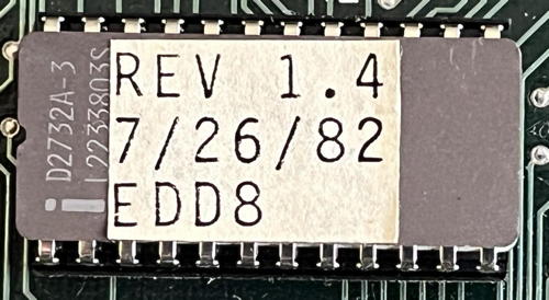
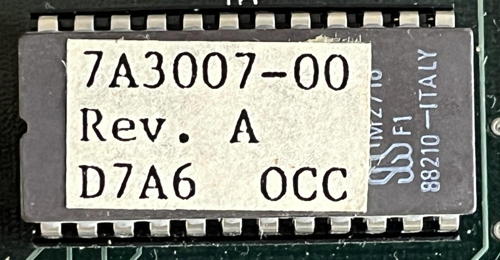
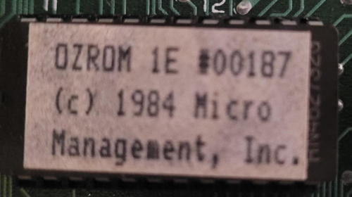
[29-Aug-2024: tested successfully]
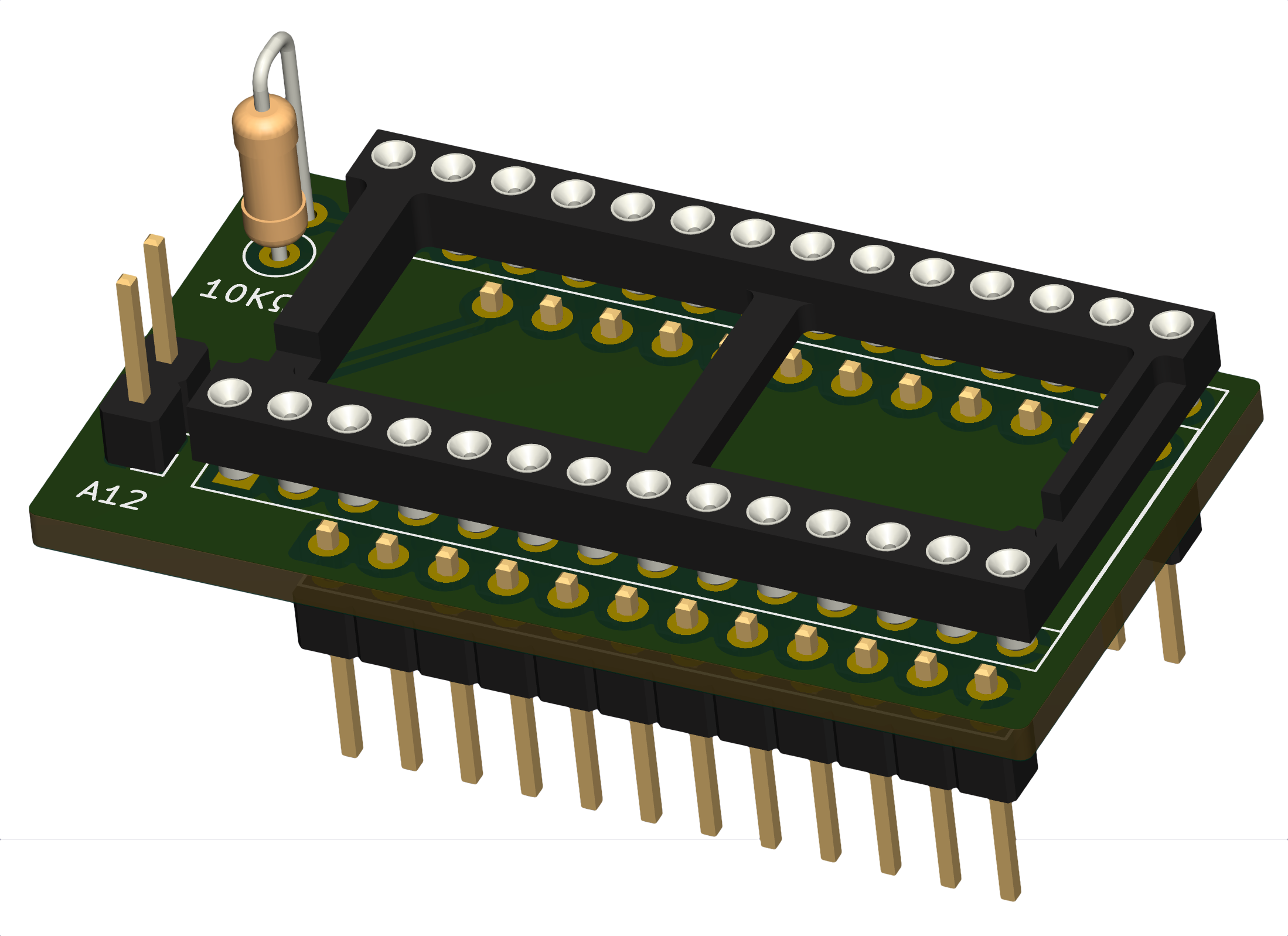
ROM daughterboard to accomodate 28-pin 2764 (8KByte) EPROM in the Osborne's 24-pin 2732 (4KByte) BIOS socket. Idea is to allow switching between the official Osborne ROM and the 3rd party OZROM.
Address pin A12 is pulled high by the 10KΩ resistor (so default is upper ROM address range 0x1000 to 0x1FFF) or can be switched to ground via a strapping or switch connected to the A12 pin header (so lower ROM address range 0x0000 to 0x0FFF).
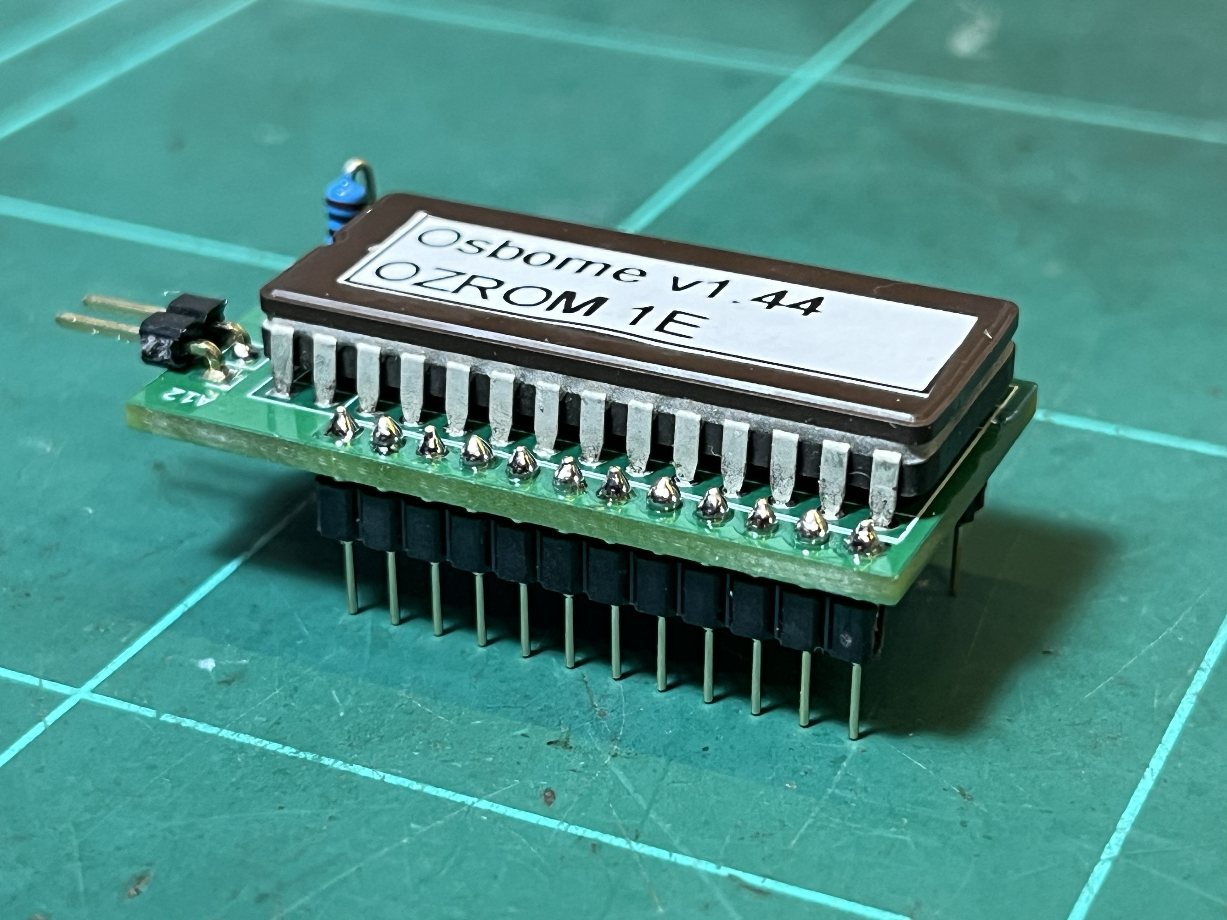
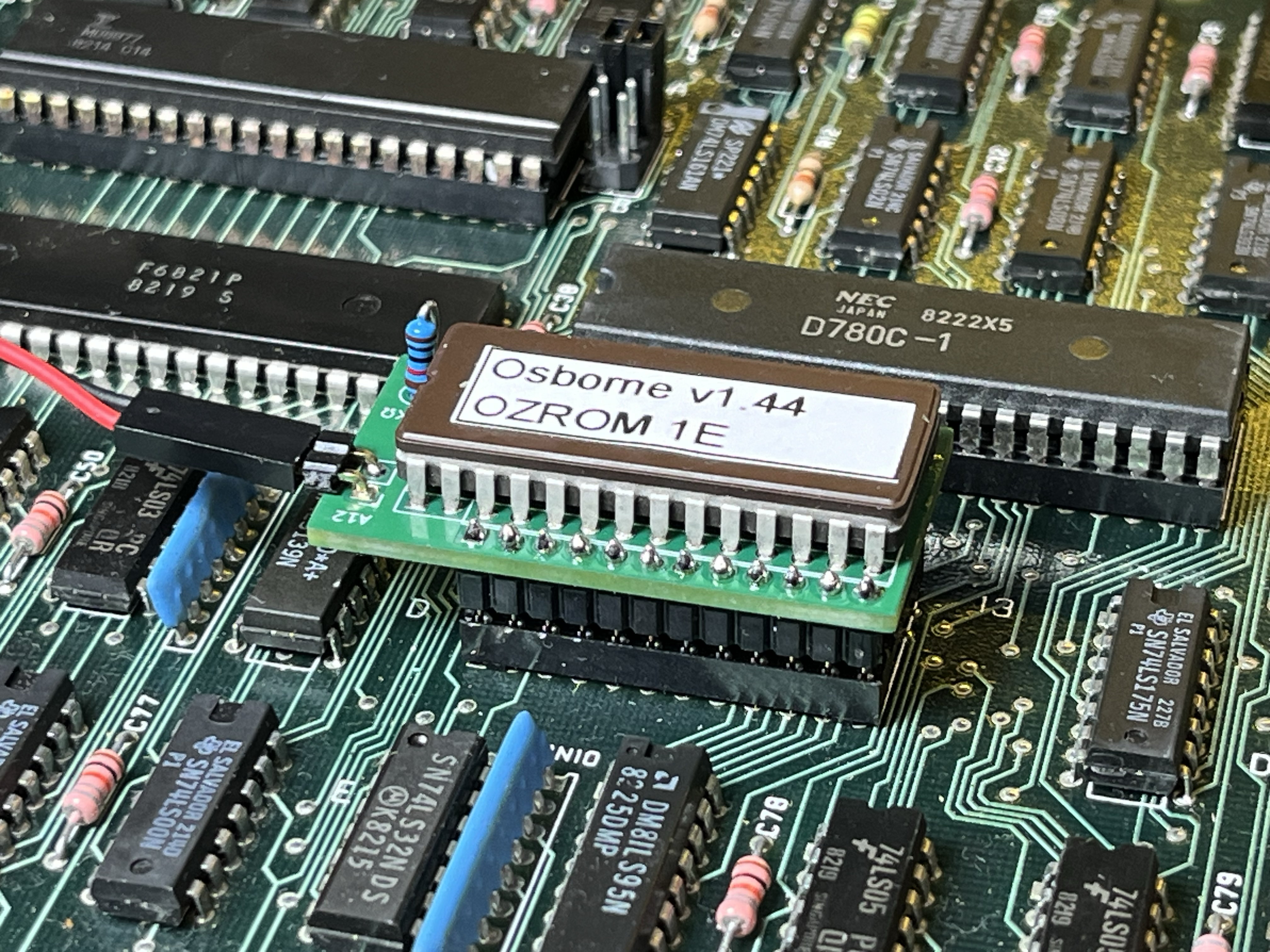
Big thanks to Dave Dunfield for the original ImageDisk-format (IMD) disk images.
How to tell if an Osborne 1 disk image is single density (SD) or double density (DD)?
Both disk formats have 40 tracks:
Example output of fsed.cpm info command on an IMG disk image:
              Sector length: 1024
           Number of tracks: 40
Sectors per track: 5Photos of the EXMON video output shunt.
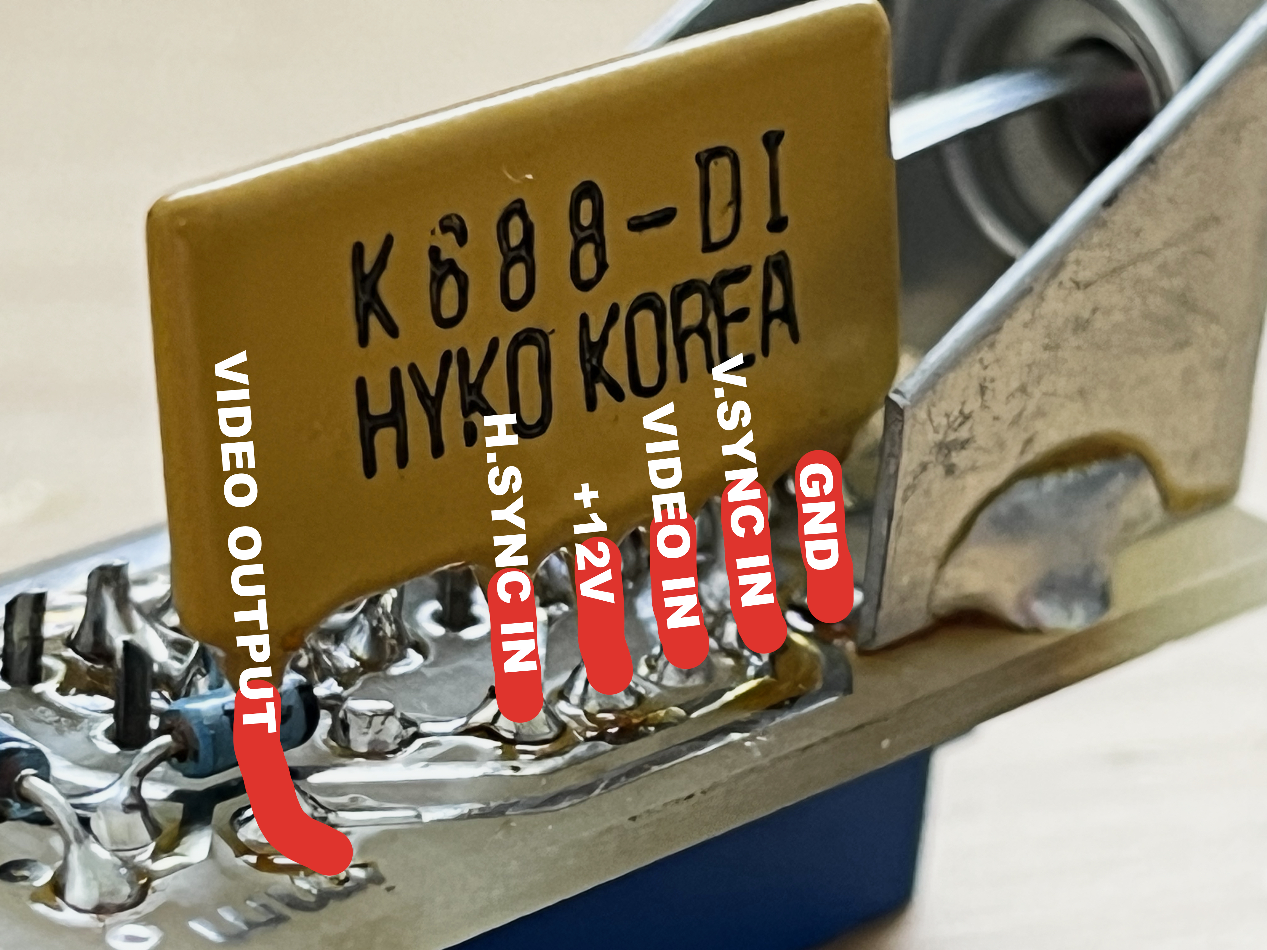
Photos of the original Osborne DD upgrade board and details of a modern reproduction board.
Photos of the Screen Pac board.
| Qty | Value | Footprint | References |
|---|---|---|---|
| 1 | 10KΩ | Resistor_THT:R_Axial_DIN0207_L6.3mm_D2.5mm_P2.54mm_Vertical | R1 |
| 1 | 2732_ROM_Socket | Open2327RomAdapter:DIP-24_W15.24mm-Notch | J1 |
| 1 | 2764 | Package_DIP:DIP-28_W15.24mm_Socket | J2 |
| 1 | A12 | Connector_PinHeader_2.54mm:PinHeader_1x02_P2.54mm_Vertical | J3 |

joypad-ai/joypad-os
Universal controller firmware for building adapters, dongles, and custom controllers.


hackclub/OnBoard
💡 Join 1,000 teenagers and make your first PCB with a $100 grant!

tardate/LittleArduinoProjects
a collection of "Little Electronic & Arduino Projects", most involving electronics or an Arduino in one way or another!

drandyhaas/KiCadRoutingTools
A set of Python/Rust tools to aid routing in KiCad

osy/XG_Mobile_Station
Open source eGPU dock for ROG Ally and ROG Flow

Luos-io/luos_engine
Open-source and real-time orchestrator for cyber-physical-systems, to easily design, test and deploy embedded applications and digital twins.

NVNTLabs/switch2-SDEX2M2
Micro SD Express to M.2 NVME Adapter for Nintendo Switch 2
It measures 42.4 × 22.4 mm and has 2 copper layers, 1.6 mm thick.
4 parts. The full list of its parts is on this page, with links to each part's symbol and footprint where PCBKit's library has them.
From the BrettHallen/Osborne_1 repository on GitHub, at the commit this page was made from: the board is 2732-to-2764/RevA/Osborne_2732_to_2764.kicad_pcb and its schematic 2732-to-2764/RevA/Osborne_2732_to_2764.kicad_sch. PCBKit opens the board in the browser, with nothing to install.
Its repository states no licence, so its author keeps all rights: ask BrettHallen before reusing the design.