
2 layers60 × 30 mm
Controller
google/mozc-devices
Circuit diagrams and firmware source code for Gboard DIY keyboards
11 parts3kApache-2.0

Simulated mainframe computer based on a Raspberry Pi
LEDs is an open-source printed circuit board by BrentSeidel, from the BrentSeidel/Pi-Mainframe repository on GitHub, published under the GPL-3.0 licence. It is a 2-layer board of 152 × 19.3 mm with 11 parts on 9 nets, routed with 39 tracks and 0 vias.
Its parts include 8 diodes and 1 connector.
Simulated mainframe computer based on a Raspberry Pi
[
When I was a young lad, computers had complicated panels filled with switches and lights. Sadly, these disappeared as I got older.
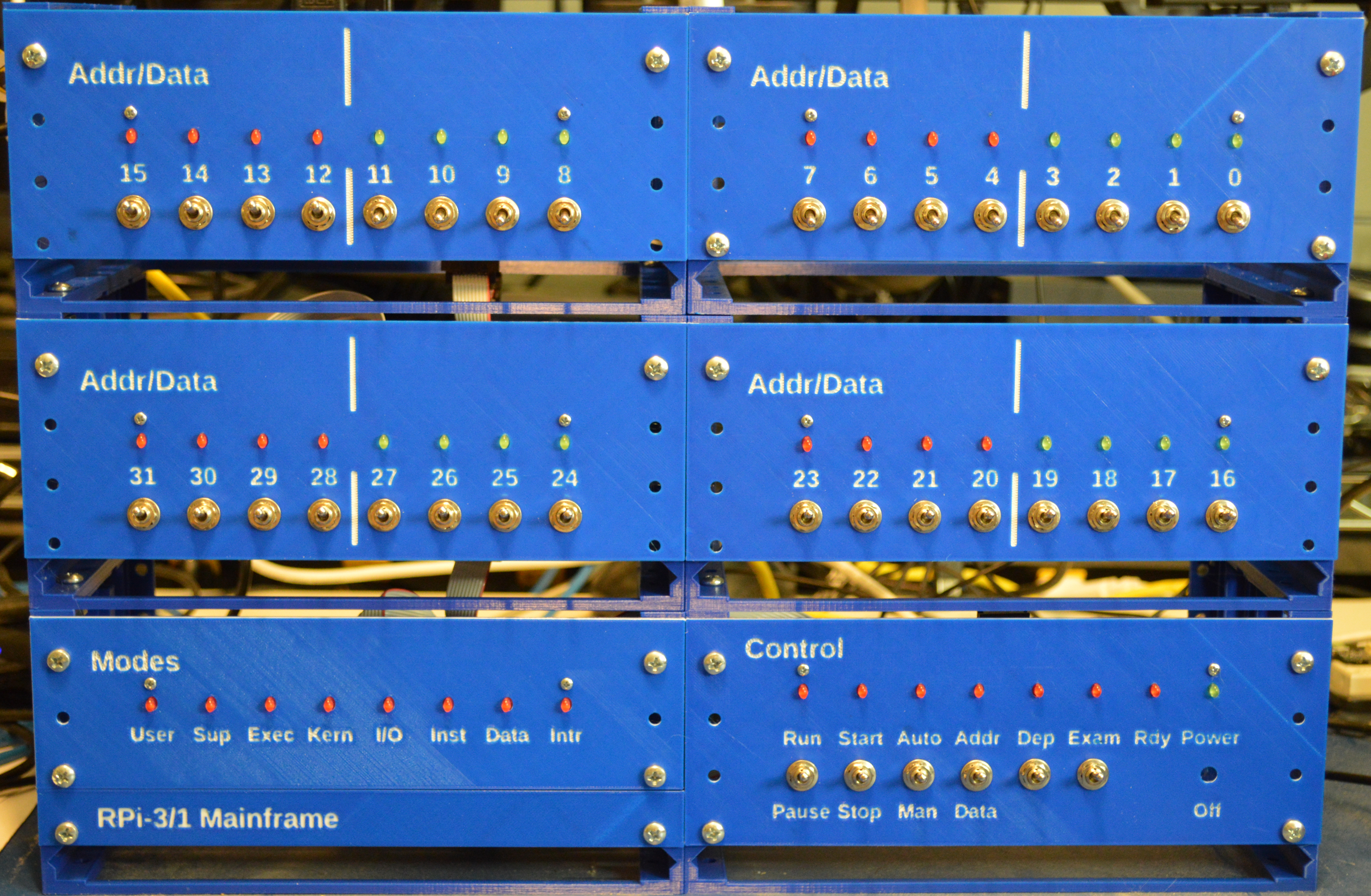
This project is an attempt to recreate the feel of old mainframe computers using a Raspberry Pi 3 and some other assorted parts that I had laying around. The actual boxes and panels are 3D printed.
Here is an example system. Note that it is fairly modular and the
modules can be attached in different ways.
Back of system
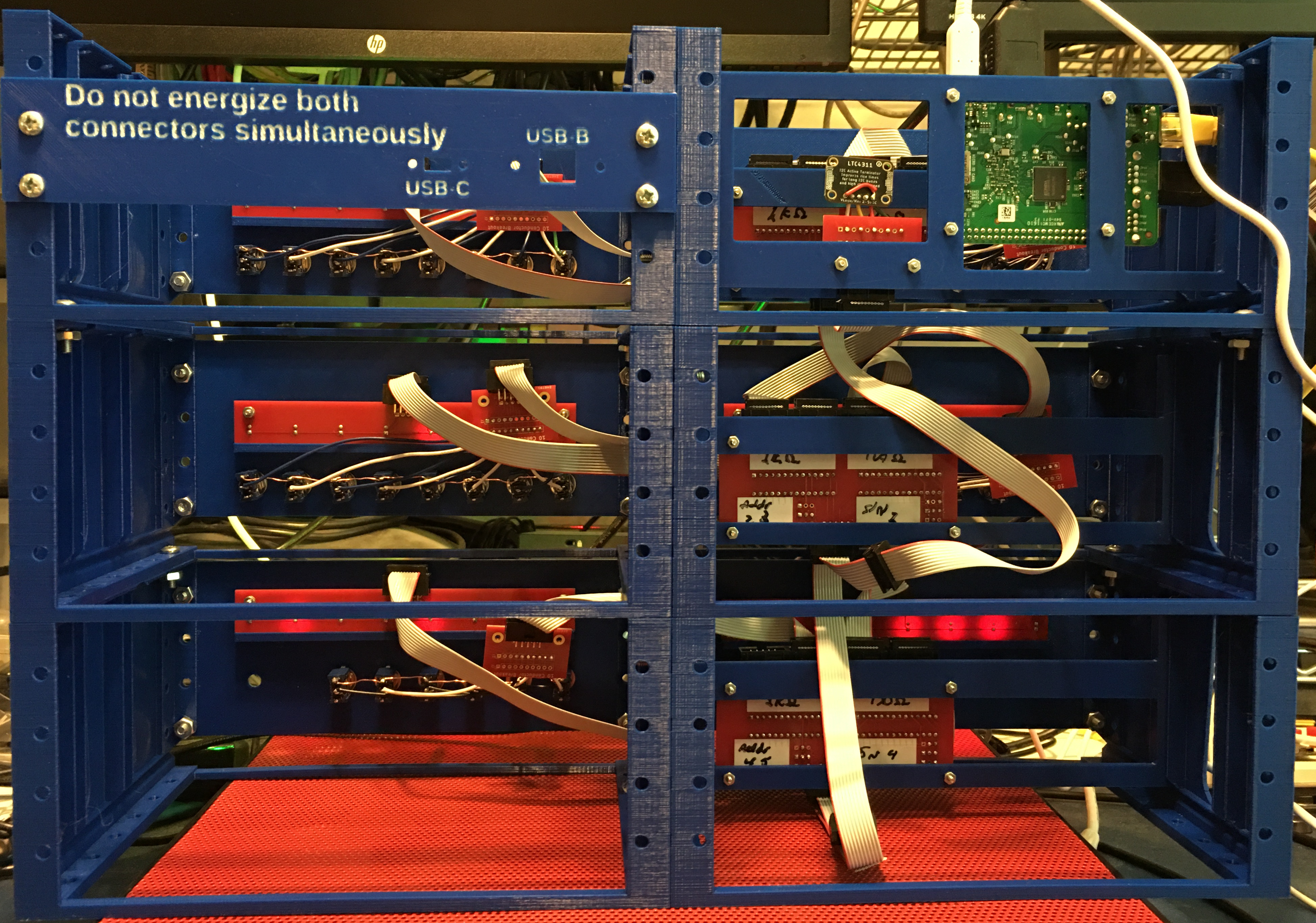
This is still very much a work in progress and things will change.
This project requires 3D printing, making PCBs, soldering, and building software from source. It might be a good project for an undergraduate engineering program.
I originally used a random micro USB power supply for the Pi 3 that is running the simulation. It would complain about low voltage and occasionally reboot. I just replaced it with the official Raspberry Pi power supply and it is not complaining about low voltage. Time will tell if it is more stable.
Ultimately, there will be limits to how much power you can get out of the Raspberry Pi. There are ways to reduce the power needed. The first thing that I would try would be to increase the value of the resistors for the LEDs. This would also reduce the brightness so you may wish to do this as well, if the LEDs are too bright. A little experimentation will be needed to determine the proper value. From a BOM viewpoint, using the same resistors for both the switches and LEDs would be a win.
Three printed circuit boards have been designed to eliminate some of the tedious soldering. Using the PCBs make assembly much easier and the resulting project much less of a mess of wires.
The I/O board PCB has been created and tested. The schematics and PCB layout have been moved to the Circuits reporitory. Documentation and assembly instructions for it have been created there.
A breakout PCB has been developed for breaking out the 10 conductor ribbon cables that are being used for the I2C bus, and other uses. It is also in the Circuits repository.
A PCB has been developed for holding the LEDs. This required some redesign to the panels. However it eliminates the soldering of wires directly to the LED leads. The LED PCB can also be fairly easily added to and removed from panels should you wish to, for example, use LEDs of different colors.
This depends on the following repositories:
If you are actually interested in simulating old computers, you can download and build simh from github at https://github.com/simh/simh.git I was able to get the PDP-11 sim to build (I haven't tried others) and run on a Raspberry Pi. As far as I know, it has no support for blinking lights.
You could, of course run simh in parallel with this project giving a CPU simulation as well as lights and switches. Unfortunately, they would be completely independant. Someday, perhaps this will change.
This project will require quite a bit of 3D printing and soldering. The included documentation includes a parts list. Read the documentation first, then download the dependencies repositories. Finally decided how big of a system you want.
| Qty | Value | Footprint | References |
|---|---|---|---|
| 8 | LED | LED_THT:LED_D5.0mm_Clear | D1, D2, D3, D4, D5, D6, D7, D8 |
| 2 | MountingHole_2.5mm_Pad | MountingHole:MountingHole_2.5mm_Pad | REF1, REF2 |
| 1 | Conn_02x05_Odd_Even | Connector_PinHeader_2.54mm:PinHeader_2x05_P2.54mm_Horizontal | J1 |
google/mozc-devices
Circuit diagrams and firmware source code for Gboard DIY keyboards


FrameworkComputer/ExpansionCards
Reference designs and documentation to create Expansion Cards for the Framework Laptop

hoglet67/RGBtoHDMI
Bare-metal Raspberry Pi project that provides pixel-perfect sampling of Retro Computer RGB/YUV video and conversion to HDMI

hackclub/OnBoard
💡 Join 1,000 teenagers and make your first PCB with a $100 grant!


tardate/LittleArduinoProjects
a collection of "Little Electronic & Arduino Projects", most involving electronics or an Arduino in one way or another!

basilfx/TRADFRI-Hacking
Hacking IKEA TRÅDFRI products, such as light bulbs, window blinds and other accessories.
It measures 152 × 19.3 mm and has 2 copper layers, 1.6 mm thick.
11 parts. The full list of its parts is on this page, with links to each part's symbol and footprint where PCBKit's library has them.
From the BrentSeidel/Pi-Mainframe repository on GitHub, at the commit this page was made from: the board is Schematics/LEDs/LEDs.kicad_pcb and its schematic Schematics/LEDs/LEDs.kicad_sch. PCBKit opens the board in the browser, with nothing to install.
Its repository publishes it under the GPL-3.0 licence: you may reuse it on that licence's terms (keep the author's notice, and for a copyleft licence share your changes alike).