2 layers105 × 105 mm
Neopixel
hackclub/OnBoard
💡 Join 1,000 teenagers and make your first PCB with a $100 grant!
71 parts915

 BitlinkLabs/DRV8662-breakout3
At the output you can connect a piezo actuator for haptic feedback or valves & pumps. The output voltage is an AC Waveform with an adjustable Peak-to-Peak voltage.
DRV8662 Breakout Rev2.1 is an open-source printed circuit board by BitlinkLabs, from the BitlinkLabs/DRV8662-breakout repository on GitHub. It is a 2-layer board of 40 × 36 mm with 71 parts on 26 nets, routed with 134 tracks and 97 vias.
Its parts include 19 resistors, 9 capacitors, 3 connectors, 1 IC and 1 diode. It belongs with the interfaces and adapters boards of this library.
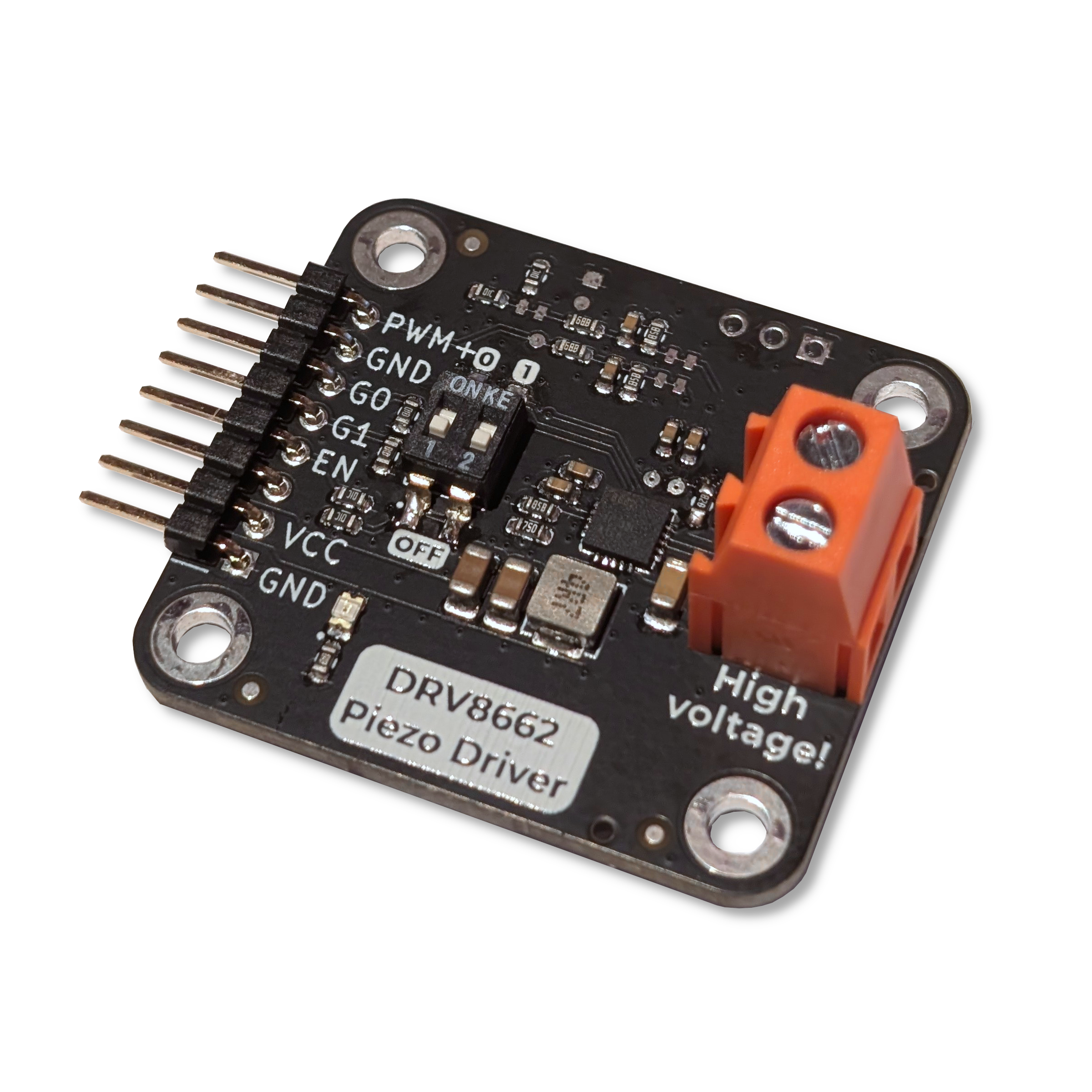
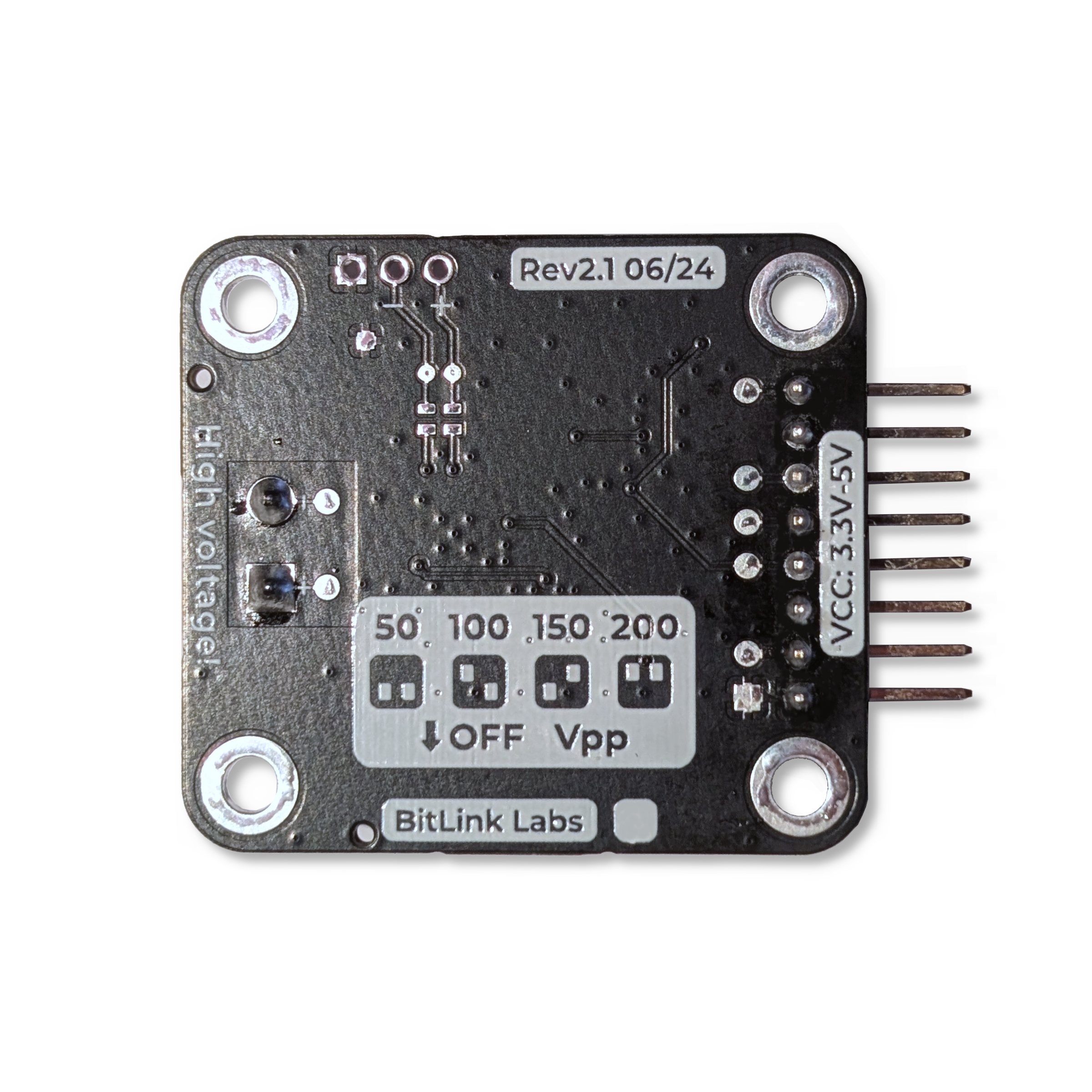
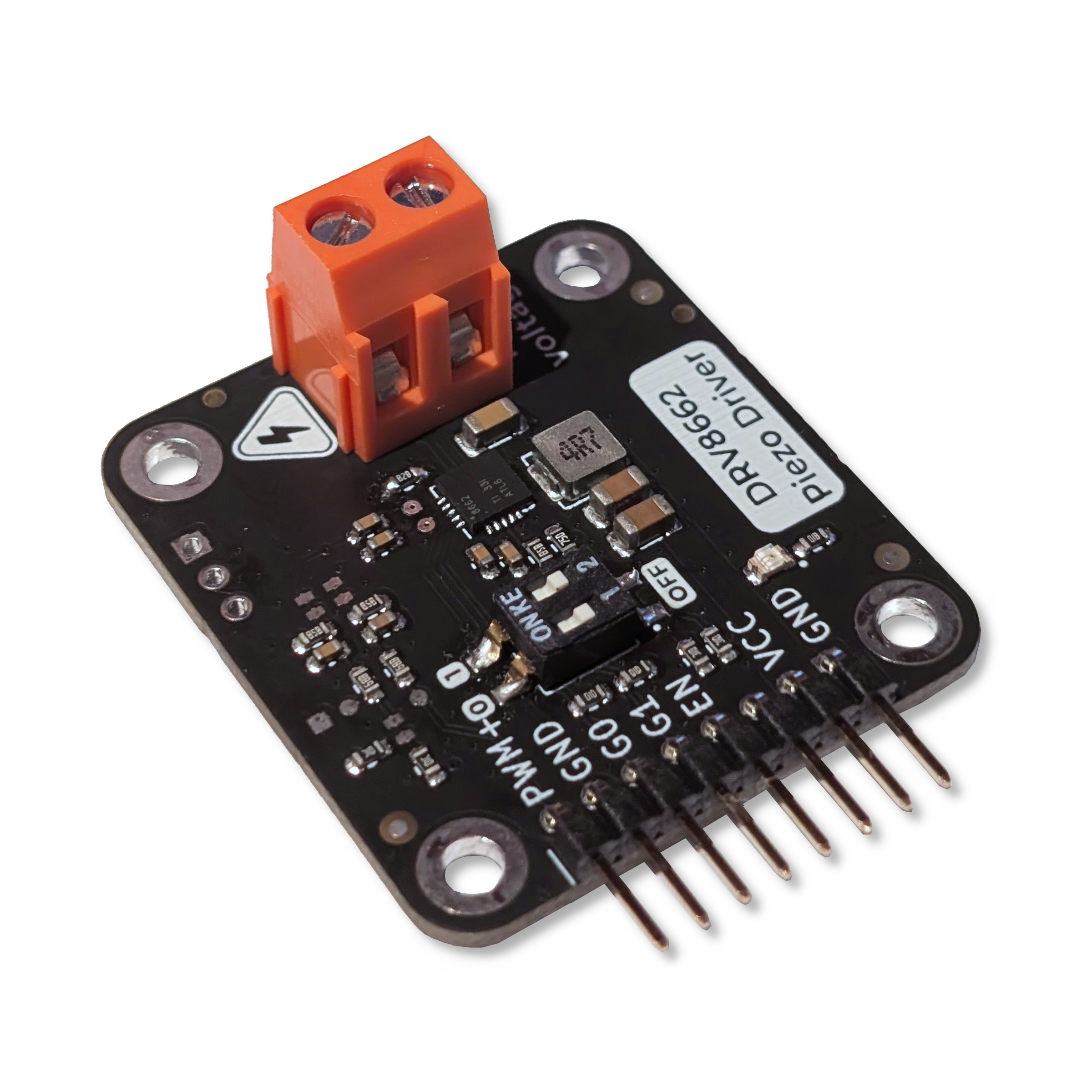
This is a ready-to-go development board with everything necessary to run piezo actuators. It features a DRV8662 IC from Texas Instruments and all the additional circuitry for it to work as expected.
The IC serves multiple purposes. First of all it is a boost-converter to generate up 200V from the 3.3-5V it takes as an input. Secondly it features an amplifier which takes a PWM Signal and drives the Output pins to the respective differential values according to the input.
At the output you can connect a piezo actuator for haptic feedback or valves & pumps. The output voltage is an AC Waveform with an adjustable Peak-to-Peak voltage.
The Output voltage can be to 4 approximate values: 50Vpp, 100Vpp, 150Vpp, 200Vpp using a simple dip switch.
All you need to do is connect an PWM and GND pin of a microcontroller to the PWM+ Pin and GND pin of the development board respectively. This covers the “signal” part. To power the dev board you can either use the USB mini jack (we recommend using a USB hub for this) or through the included VCC and GND Pins. Be sure to stick to an input voltage of 3.3V to 5V and be aware that the USB voltage will be present on the VCC pin.

| Qty | Value | Footprint | References |
|---|---|---|---|
| 13 | LOGO | LOGO | G***, G***, G***, G***, G***, G***, G***, G***, G***, G***, G***, G***, G*** |
| 7 | TestPoint | MAINTECH_Connectors:TestPoint_Pad_D1.5mm_NoSilk | TP9, TP10, TP11, TP12, TP13, TP14, TP16 |
| 6 | 100nF | Capacitor_SMD:C_0603_1608Metric | C1, C2, C5, C6, C7, C8 |
| 6 | TestPoint | MAINTECH_Connectors:TestPoint_Pad_D1.0mm_NoSilk | TP1, TP2, TP4, TP5, TP7, TP8 |
| 4 | 10k | Resistor_SMD:R_0603_1608Metric | R1, R6, R7, R16 |
| 4 | MountingHole | MountingHole:MountingHole_3.2mm_M3_ISO7380_Pad_TopBottom | H1, H2, H3, H4 |
| 3 | 0R | MAINTECH_Connectors:Jumper_Small-2_bridged | R8, R12, R13 |
| 3 | 7.5k | Resistor_SMD:R_0603_1608Metric | R4, R10, R11 |
| 3 | Fiducial | MAINTECH_mechanical:Fiducial_standart | FID1, FID2, FID3 |
| 2 | 0R | MAINTECH_Connectors:Jumper_Small-2_open | R17, R18 |
| 2 | 100k | Resistor_SMD:R_0603_1608Metric | R14, R15 |
| 2 | 10uF | Capacitor_SMD:C_1206_3216Metric | C9, C10 |
| 2 | 4.99k | Resistor_SMD:R_0603_1608Metric | R5, R9 |
| 2 | TestPoint | TestPoint:TestPoint_Pad_1.0x1.0mm | TP3, TP6 |
| 1 | 100nF | Capacitor_SMD:C_1206_3216Metric | C3 |
| 1 | 1k | Resistor_SMD:R_0603_1608Metric | R19 |
| 1 | 4.7uH | MAINTECH_Passives:Inductor_FXL0420-4R7-M | L1 |
| 1 | 590k | Resistor_SMD:R_0603_1608Metric_Pad0.98x0.95mm_HandSolder | R3 |
| 1 | 6.98k | Resistor_SMD:R_0603_1608Metric_Pad0.98x0.95mm_HandSolder | R2 |
| 1 | Conn_AC | Connector_PinHeader_2.54mm:PinHeader_1x03_P2.54mm_Vertical | J6 |
| 1 | Conn_IO | MAINTECH_Connectors:PinHeader_1x08_P2.54mm_Horizontal_withSmdPads | J1 |
| 1 | Conn_Screw | MAINTECH_Connectors:DB128L-5.08-2P | J2 |
| 1 | DRV8662 | Package_DFN_QFN:Texas_S-PVQFN-N20_EP2.7x2.7mm_ThermalVias | U1 |
| 1 | LED_Small | LED_SMD:LED_0805_2012Metric | D1 |
| 1 | SW_Gain | MAINTECH_mechanical:SW_DIP_x02_P2.54_W5.08_C6709488 | SW1 |
| 1 | TestPoint_Alt | TestPoint:TestPoint_Pad_1.5x1.5mm | TP15 |
hackclub/OnBoard
💡 Join 1,000 teenagers and make your first PCB with a $100 grant!


hydrabus/hydrabus
HydraBus open source multi-tool for anyone interested in learning/developping/debugging/hacking/Penetration Testing for basic or advanced embedded hardware

beekeeb/Allium58
The Allium58 is created based on the Lily58 Pro, designed to enhance wireless capabilities and provide compatibility with GLP (Gateron Low Profile) hotswap sockets.


siderakb/ergo-snm-keyboard
ErgoSNM is a split ergonomic keyboard integrated with trackball, wireless is in beta

cnlohr/cnhardware
My dumping grounds for all my kicad projects and random hardware bringup.
It measures 40 × 36 mm and has 2 copper layers, 1.6 mm thick.
71 parts. The full list of its parts is on this page, with links to each part's symbol and footprint where PCBKit's library has them.
From the BitlinkLabs/DRV8662-breakout repository on GitHub, at the commit this page was made from: the board is DRV8662_Breakout_Rev2.1.kicad_pcb and its schematic DRV8662_Breakout_Rev2.1.kicad_sch. PCBKit opens the board in the browser, with nothing to install.
Its repository states no licence, so its author keeps all rights: ask BitlinkLabs before reusing the design.