2 layers117.3 × 54.5 mm

 Biacco42/Ergo42218
7x4 ortho linear split keyboard - The Answer to the Ultimate Question of Life, the Universe, and at least Keyboards
Ergo42 is an open-source printed circuit board by Biacco42, from the Biacco42/Ergo42 repository on GitHub. It is a 2-layer board of 135.9 × 102.2 mm with 69 parts on 51 nets, routed with 589 tracks and 13 vias.
Its parts include 29 switches, 28 diodes, 6 ICs, 2 resistors and 1 connector. It belongs with the keyboards and input boards and the AVR (ATmega, ATtiny) boards of this library.
The Answer to the Ultimate Question of Life, the Universe, and at least Keyboards.
7x4 ortho linear split keyboard.
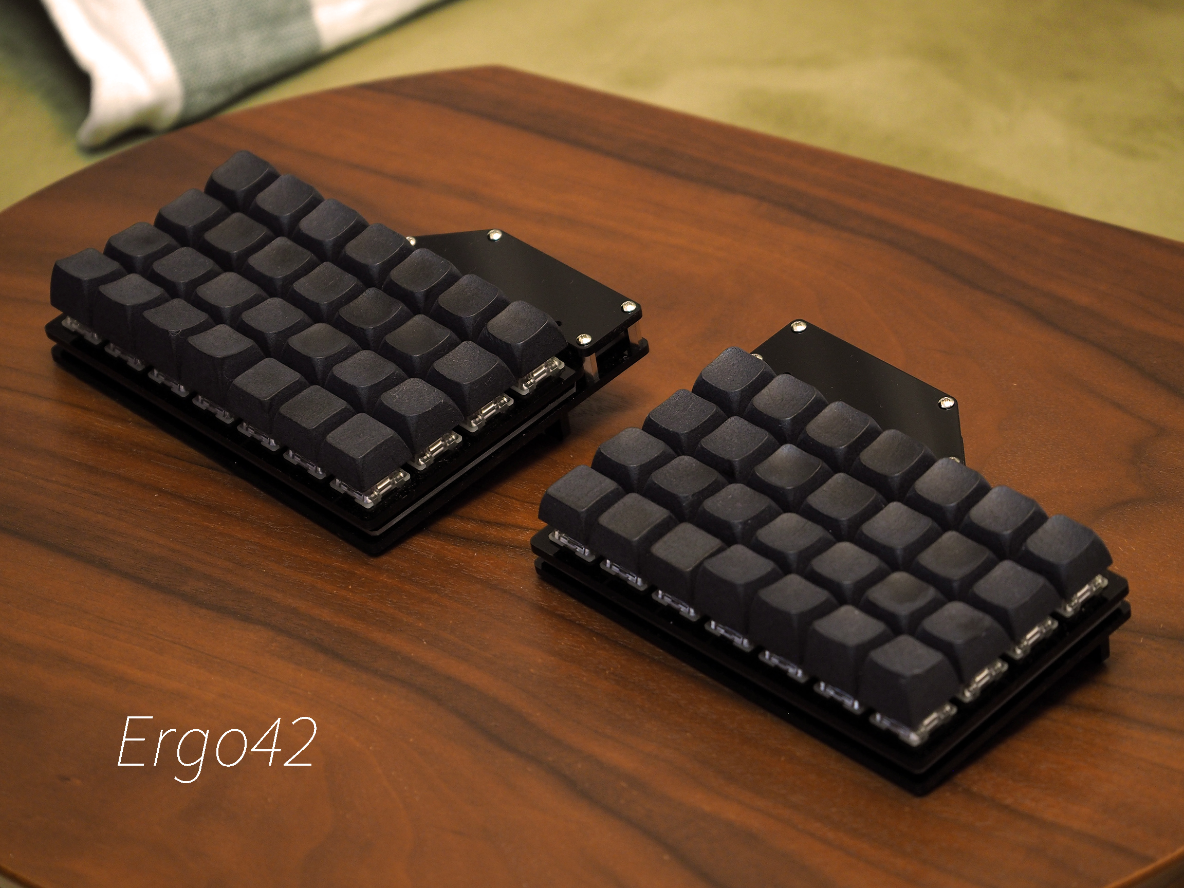
Caution! Ergo42 after version 3.0.0 Towel is not compatible with both version 1 and 2 series design. If you build Ergo42 not version 3 Towel series, please refer to the 1.x or 2.x branch.
The screws may have a slight clearance issue with the keycaps. Use a screw with a lower profile head.
Place the PCB as TRRS jacks on the inside, closest to one another.
Which side you solder the diodes on depends on your switch plate's thickness and key switch type, which is Cherry MX compatible or Kailh low profile. Acrylic plate thickness < 3 mm with Cherry MX compatibles should have diodes on the same side as the key switches. Acrylic plate with Kailh low profile switches should have diodes on the opposite side of the key switches.
Double check your work. Black lines (THD) / White lines (SMD) should be facing the square pad.
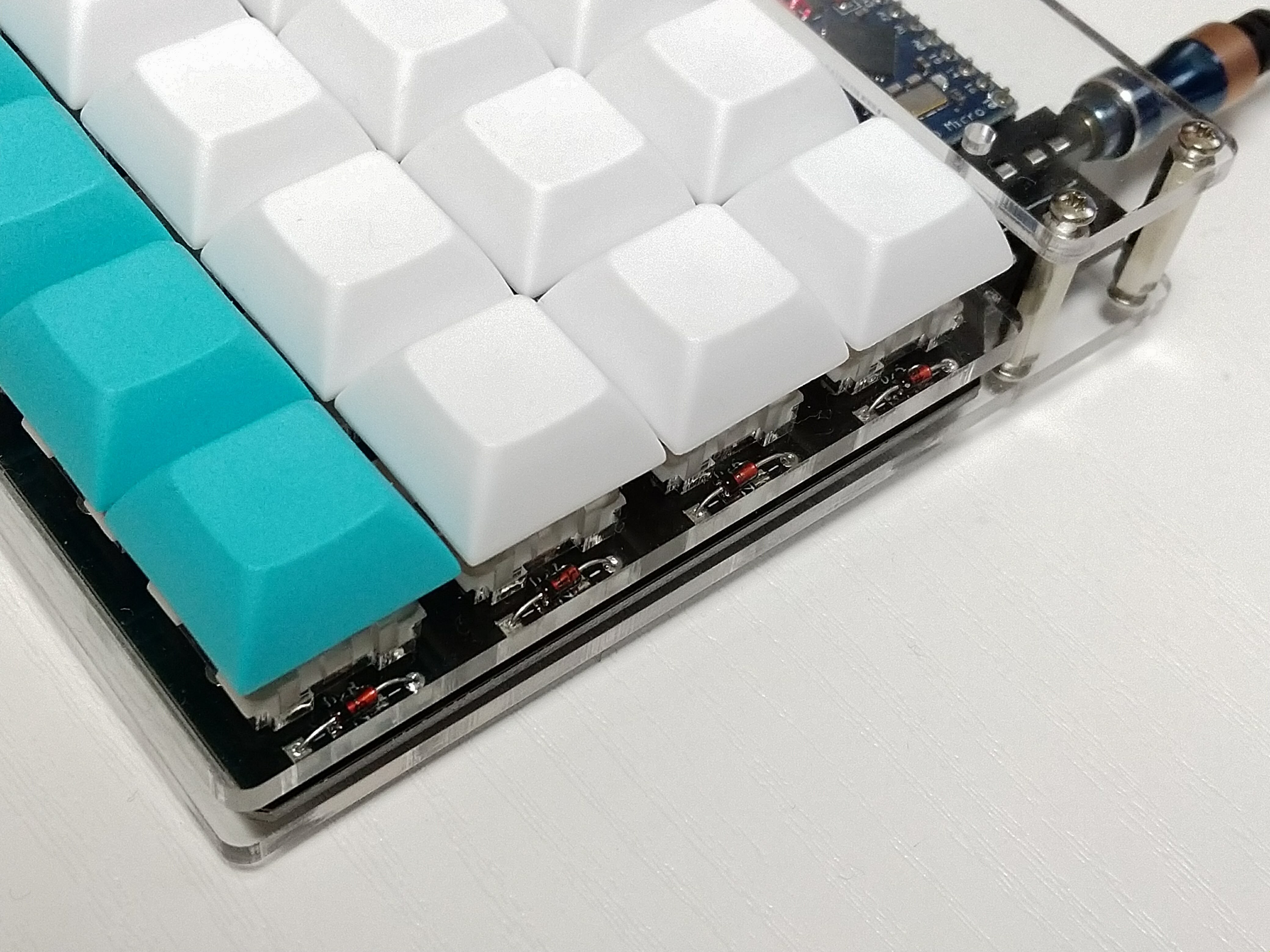
If you want to use I2C, not UART, to comunicate with other side PCB, you should add 2.2 k ohm resistors on the left side PCB's R1 and R2 printed silk. Also bridge to short W1 pad by solder jumper on each side PCB. Usually you don't have to do this step.
Mount the TRRS jack and tact switch on the same side as your switches. It should be on the upper face.
Ergo42's PCB is symmetrical but Pro Micro mount is different between the left and right PCB. This spec is changed from version 2.
Solder pin headers on the Pro Micro's component side. Both left side and right side one are same.
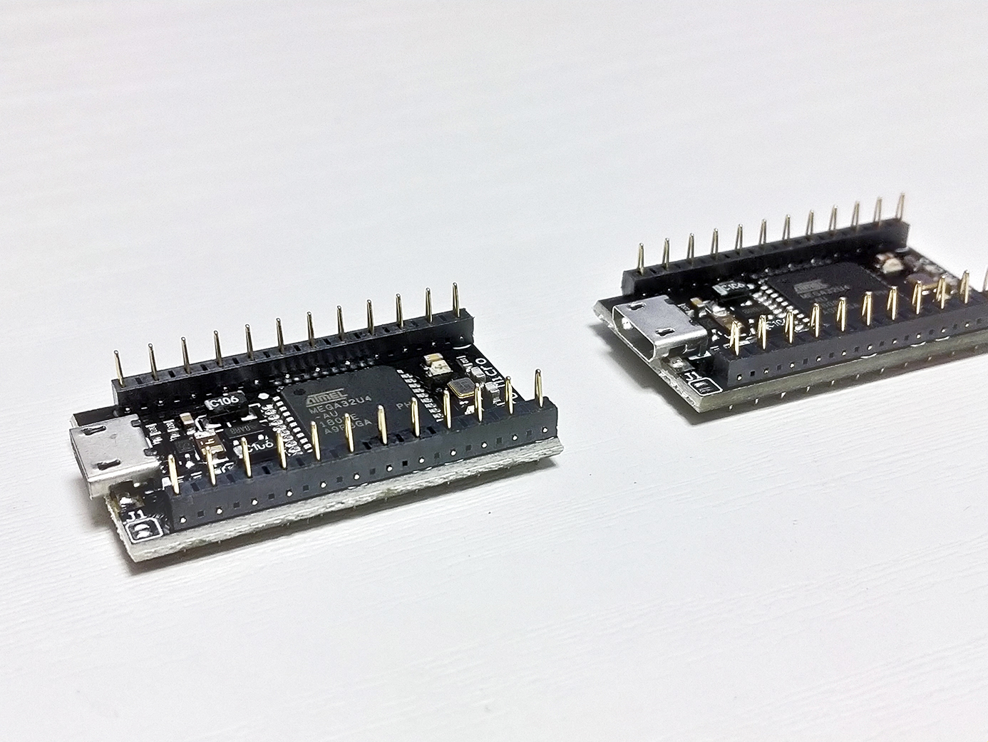
If you use through hole connectors, you should solder that on the Pro Micro board, not on the PCB.
The through hole connector has sides and directions. There is recommended mount direction.

Please mount the through hole connector on the Pro Micro referencing the direction on the image above. Also be careful to mount the through hole connectors to face same side on same direction. You can see the holes on both through hole connectors simultaneously. Please check that the holes of the through hole connector is visible at the same time in the image below.
Solder (or set when you use through hole connector) the Pro Micro on the PCB in the white line silk.
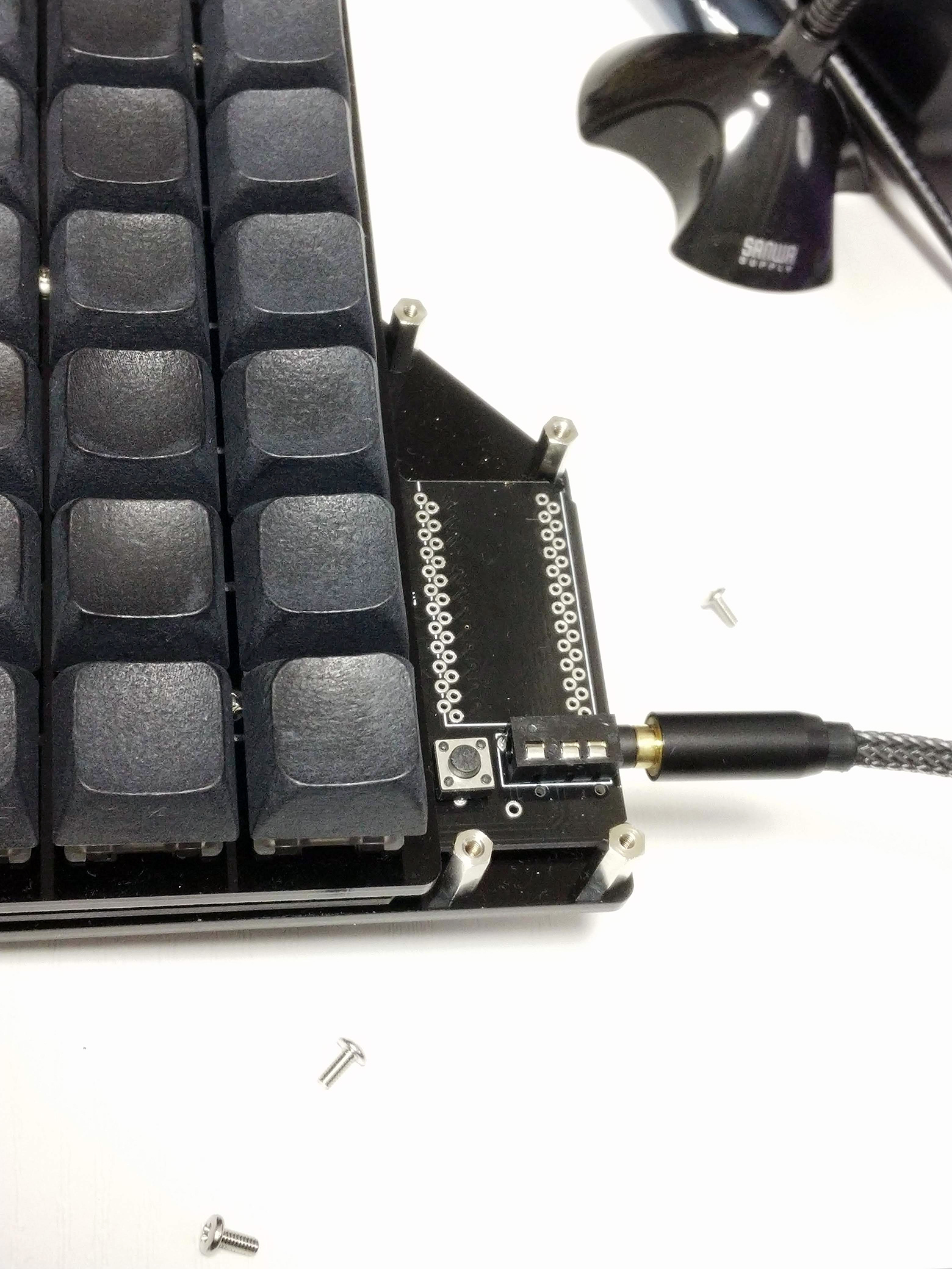
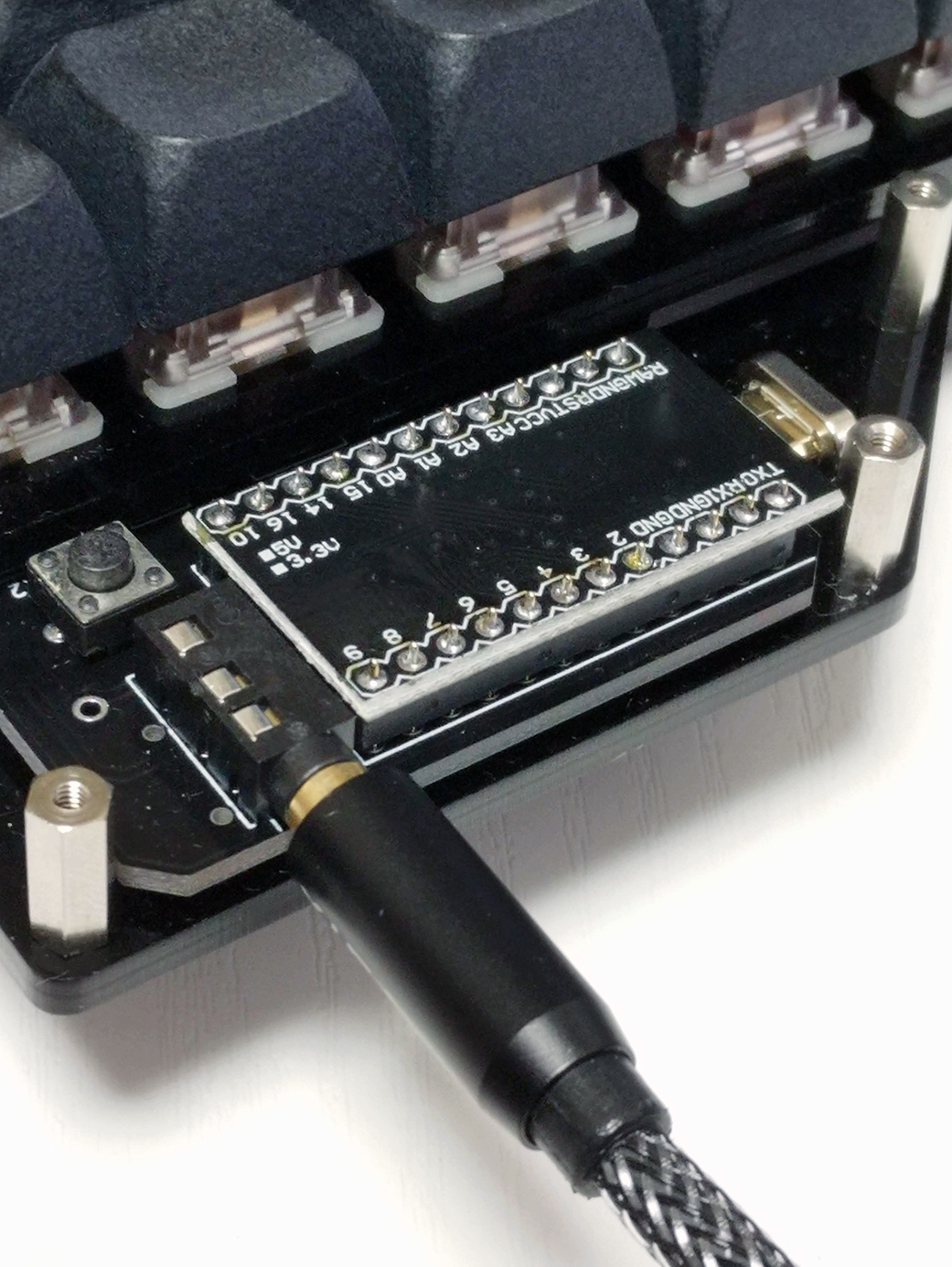
Be careful to refer the white line on the Pro Micro side (not soldering side).
Mount switches on the acrylic plate, set PCB to fit and solder switches.
When you use Cherry MX compatibles with Acrylic plate thickness < 3 mm and 5 mm height stand-offs, please cut off the tip of the electricity terminal of the switch. The electricity terminal of the switch interferences with bottom plate.
Tighten the screws with standoffs. Some vinyl pads may help the keyboard's stability. Install your keycaps.
From version 3 Towel, there are some tent/tilt leg options. You can set the legs and put on some silicon tape for stability.
Now you can flash the pre-built firmware that supports VIA / Remap keymap edit in Remap.
https://remap-keys.app/catalog/unf8swoIgYlDVLGyN9H6
QMK firmware for Ergo42 is now available on QMK firmware. This document doesn't cover how to build QMK. Prease refer to QMK documents.
Connect the keyboard by USB cable to a PC and run
$ make ergo42:default:avrdudeon the left and right side keyboard individually.
It will build and try to flash your firmware. Follow the instructions that require to reset the Pro Micro.
This process may require privileges. If you have some Permission denied error, please try
$ sudo make ergo42/rev1:default:avrdude| Qty | Value | Footprint | References |
|---|---|---|---|
| 28 | D | library:Diode_SMD_THT | D1, D2, D10, D11, D12, D13, D14, D15, D16, D17, D18, D19, D20, D21, D22, D23 +12 |
| 28 | SW_PUSH | library:key_switch | SW1, SW2, SW10, SW11, SW12, SW13, SW14, SW15, SW16, SW17, SW18, SW19, SW20, SW21, SW22, SW23 +12 |
| 5 | HOLE | library:hole | U1, U2, U4, U5, U7 |
| 2 | LOGO | library:ergo42_logo | G***, G*** |
| 2 | R | Resistors_THT:R_Axial_DIN0207_L6.3mm_D2.5mm_P10.16mm_Horizontal | R1, R2 |
| 1 | 5PIN | library:trrs_jack | J1 |
| 1 | ProMicro | promicro:ProMicroReversible | U3 |
| 1 | SW_Push | library:tact_switch | SW29 |
| 1 | jumper_smd | library:jumper_smd_2dub | W1 |

jackw01/scanlight
A better light source for scanning color negative film

eigenco/frankenpi
This is an experimental project to connect Raspberry Pi with the help of cheap Cyclone IV FPGA board to 8-bit ISA bus to act as multiple different devices.

mattybrad/drumkid
Version 4 was the first successful working design, with full code, schematics, Gerbers, etc available on GitHub.

KaiPereira/Overglade-Badges
NFC hackathon badges for the Overglade game jam in Singapore!

BerkeleyHCI/PolymorphicBlocks
A Python-based hardware description language for PCBs for higher-level (block-diagram / system-architecture level) PCB design through libraries of directly reusable subcircuit generators.


It measures 135.9 × 102.2 mm and has 2 copper layers, 1.6 mm thick.
69 parts. The full list of its parts is on this page, with links to each part's symbol and footprint where PCBKit's library has them.
From the Biacco42/Ergo42 repository on GitHub, at the commit this page was made from: the board is ergo42/ergo42.kicad_pcb. PCBKit opens the board in the browser, with nothing to install.
Its repository states no licence, so its author keeps all rights: ask Biacco42 before reusing the design.