Skip to the content
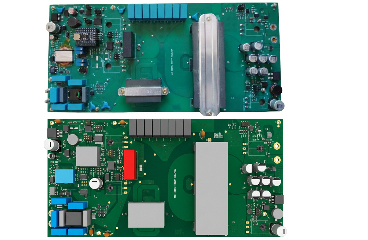
4 layers140 × 300 mmLLC DCDC V5, the printed circuit board in 3D

In battery electric vehicles (BEVs) and 48 V mild-hybrid architectures, a high-voltage DC-DC converter steps the 300–400 V traction battery bus down to the 48 V auxiliary rail that powers lighting, HVAC blowers…

Size
140 × 300 mm
Copper layers
4
Thickness
1.6 mm
Parts
212
Nets
126
Pads
655
Tracks, vias
964, 2,474
Pours
23
Routed
Yes
KiCad
KiCad 10.0 (file 20260206)
Created
23 Jun 2025
Updated
2 Aug 2026

Overview

LLC DCDC V5 is an open-source printed circuit board by BOAB235, from the BOAB235/Design_of_1200W_LLC_DCDC repository on GitHub. It is a 4-layer board of 140 × 300 mm with 212 parts on 126 nets, routed with 964 tracks and 2,474 vias.

It is built around the ACS70331EOLCTR-005U3, LM2575-3.3WU-TR and SI82390BD-IS, with the SI8932B-IS, TMCS1107A1UQDRQ1 and AZ1117CH2-3.3TRG1 among its other parts. Its parts include 87 capacitors, 42 resistors, 14 ICs, 7 connectors and 6 diodes. It belongs with the power boards and the STM32 boards of this library.

Main components

12

README

README.md

1200 W · 400 V → 48 V · LLC Resonant DC-DC Converter

Open-Source Hardware Design for Electric-Vehicle Auxiliary Power

License: MIT


1200W LLC DC-DC Converter

A complete, open-source hardware project — from analytical tank design through PCB fabrication, embedded control firmware, EMC testing, and efficiency characterization — targeting the 400 V traction bus to 48 V auxiliary rail conversion found in modern electric vehicles.


Interactive Project Page & Gallery


Table of Contents


Context & Motivation

In battery electric vehicles (BEVs) and 48 V mild-hybrid architectures, a high-voltage DC-DC converter steps the 300–400 V traction battery bus down to the 48 V auxiliary rail that powers lighting, HVAC blowers, infotainment, ADAS sensors, and body-control electronics. The LLC resonant topology is the industry-preferred choice for this role because it naturally achieves zero-voltage switching (ZVS) across the load range, yielding high efficiency, low EMI, and compact magnetics.

This project documents the complete physical design of such a converter:

  1. Analytical Design — Resonant tank optimisation, magnetic core selection, MOSFET thermal analysis, EMI filter sizing, and PCB trace calculations — all in reproducible Jupyter notebooks.
  2. Hardware Build — KiCad schematic (V5), BOM, Gerber files, and a custom PCB with planar magnetics.
  3. Embedded Control — 23 iterative firmware versions on an STM32F103C8T6, culminating in an adaptive PI controller with thermal derating (bare-metal C/C++, register-level).
  4. Test & Characterisation — EMC conducted-emissions testing (CISPR 25 setup), safety tests, LLC gain & tank characterisation, and full-load efficiency measurements.

Note: This is primarily a hardware/power-electronics project. The firmware is a supporting element written in embedded C++ on an STM32 to close the voltage-regulation loop — it is not a software product.


Key Specifications

ParameterValue
TopologyHalf-bridge LLC resonant (isolated)
Input voltage360 – 400 V DC (traction battery bus)
Output voltage42 – 54 V DC (nominal 48 V)
Rated output power1 200 W continuous
Rated output current25 A nominal
Switching frequency95 – 150 kHz (nominal ≈ 100 kHz)
Transformer ration = 4
Efficiency target≥ 95 % at nominal load
Output voltage ripple< 250 mV pp
Primary MOSFETs2 × IPW60R037CM8 (600 V, 3.7 mΩ)
Secondary MOSFETs2 × FDH055N15A (150 V, 110 A)
Output capacitors6 × 120 µF (B40910A8127M000)
Gate driverUCC21520Q
MCUSTM32F103C8T6 (Cortex-M3, 72 MHz)
Dead time≈ 100 ns (DTG register, configurable)
EMI standardCISPR 25 conducted-emissions setup
PCB revisionV5 (latest)

Repository Map

text
Design_of_1200W_LLC_DCDC/
│
├── 01_specifications/              ← System-level specification (see companion spec document)
├── 02_architecture/                ← High-level converter architecture & block diagrams
│
├── 03_hw_design/                   ── HARDWARE ──────────────────────────────────
│   ├── 01_design_justification/    ← Parametric calculations & Jupyter notebooks
│   │   ├── 01_llc_tank/                  Resonant tank (Lr, Cr, Lm, Q, fn curves)
│   │   ├── 01_transformer_and_Lr_cores/  Core selection (TDK N97 planar ferrite)
│   │   ├── 02_mosfets/                   MOSFET thermal & switching-loss analysis
│   │   ├── 03_resonant_and_output_capacitor/  Ripple, ESR, RMS current stress
│   │   ├── 04_measurements/              Sensor calibration (ADC ↔ voltage)
│   │   ├── 05_gate_driver/               Bootstrap & level-shift design
│   │   ├── 06_emi_filters/               CM choke, X/Y caps, damper network
│   │   ├── 07_power_supp/                Auxiliary flyback & LM2575 supplies
│   │   ├── 08_HeatSink/                  Heat-sink thermal-resistance sizing
│   │   ├── 09_Hw_protection/             OVP / OCP via 74HC74 flip-flop logic
│   │   └── 10_cb_calculations/           Trace width, via current, creepage
│   ├── 02_schematic_and_bom/       ← KiCad schematics, Gerbers, BOM
│   └── 03_components/              ← Datasheet library (129 parts)
│
├── 04_sw_design/                   ── EMBEDDED FIRMWARE ─────────────────────────
│   ├── 01_investigations/              STM32 & ESP32 bring-up tests
│   ├── 04_PWM_Freq_Change/             Switching-frequency modulation trials

Hardware Design

Every design choice is justified with reproducible calculations in Jupyter notebooks, supported by LTspice simulations and component datasheets.

LLC Resonant Tank

The resonant-tank parameters — resonant frequency $f_0$, inductance ratio $L_n = L_m / L_r$, quality factor $Q$ — were optimised to deliver the required voltage gain $M_g$ across the full 360–400 V input range while maintaining ZVS down to light load.

$$M_g = \left| \frac{L_n \cdot f_n^2}{\left[(L_n + 1) f_n^2 - 1\right] + j\left[(f_n^2 - 1) f_n Q_e L_n\right]} \right|$$

Notebook: 03_hw_design/01_design_justification/01_llc_tank/

PDF report: LLC Tank Design Note

Planar Magnetics

Both the main transformer ($L_m ≈ 65 \text{ µH}$) and the resonant inductor ($L_r$) use TDK N97 planar ferrite cores, chosen for low core-loss density at 100 kHz and excellent thermal conductivity. Transformer turns ratio is $n = V_{in,nom}/(2 \times V_{o,nom}) = 380/96 ≈ 4$.

Notebook: 03_hw_design/01_design_justification/01_transformer_and_Lr_cores/

PDF report: Magnetic Cores Design

Power MOSFETs

SideDeviceRating$R_{DS(on)}$Package
Primary (half-bridge)IPW60R037CM8XKSA1600 V / 60 A3.7 mΩTO-247
Secondary (sync. rect.)FDH055N15A150 V / 110 AlowTO-247

ZVS dead-time requirement: $t_{dead} \geq 16 \cdot C_{eq} \cdot f_{sw} \cdot L_m$ — set to ≈ 100 ns with margin.

Notebook: 03_hw_design/01_design_justification/02_mosfets/

Capacitor Bank

Six B40910A8127M000 (120 µF, 150 °C rated aluminium electrolytic) capacitors in parallel:

  • Total capacitance: ≥ 576 µF (with 20 % worst-case derating)
  • Equivalent ESR @ 100 kHz: 17 mΩ / 6 ≈ 2.8 mΩ (< 3.18 mΩ target)
  • Output ripple budget: < 250 mV pp (50 % capacitive + 50 % resistive split)

Notebook: 03_hw_design/01_design_justification/03_resonant_and_output_capacitor/

PDF report: Output Capacitor Design

EMI Filter (CISPR 25)

Two-stage common-mode / differential-mode filter designed for automotive conducted-emissions compliance:

ComponentValueRole
CM chokePA2750NL (400 µH)CM noise attenuation
Y capacitors4 × 2.2 nFCM return path
X capacitor100 nFDM filtering
Damper network27 Ω + 2.2 nFResonance suppression
  • CM resonant frequency: ≈ 170 kHz
  • DM LC cut-off: ≈ 425 kHz
  • Leakage inductance (DM): 1.4 µH

Design report: 03_hw_design/01_design_justification/06_emi_filters/justification.md

Gate Driver & HW Protection

  • Gate driver IC: UCC21520Q with bootstrap supply for high-side drive.
  • Fast hardware protection: 74HC74 D flip-flop latches OVP/OCP faults and disables PWM within nanoseconds — independent of firmware response time.
  • Voltage/current sensing: Resistive dividers and ACS70331 current sensor, calibrated against 12-bit ADC ($V_{out} = 0.03081 \times ADC - 0.0976$).

Design files: 05_gate_driver/ · 09_Hw_protection/

Thermal Management

Heat-sink thermal resistance sized for worst-case junction temperature of primary TO-247 MOSFETs at full 1 200 W load, with forced-air fan controlled via TIM2 PWM on the STM32.

Notebook: 03_hw_design/01_design_justification/08_HeatSink/

Schematic, PCB & BOM

Designed in KiCad. Trace widths and via counts calculated for 25 A output current with 0.5 oz – 2 oz copper options evaluated.

DocumentLink
Schematic (PDF)LLC_DCDC_V5
Gerber & LayoutGerber PDF
Bill of MaterialsBOM PDF
Modifications logModifications PDF

Source files: 03_hw_design/02_schematic_and_bom/


Embedded Firmware

The firmware is a supporting element of the hardware design — embedded C++ on an STM32, bare-metal (no HAL, no RTOS), for deterministic real-time PWM and ADC control.

text
STM32F103C8T6 @ 72 MHz
├── TIM1_CH2  (PA9)  → High-side gate drive
├── TIM1_CH2N (PB14) → Low-side gate drive   (dead-time DTG ≈ 100 ns)
├── ADC1 (PA0–PA7)   ← Vin, Vout, Isense, Temp
├── GPIO (PB10/12)   → 74HC74 flip-flop enable / reset
├── TIM2 (PA10)      → Fan PWM
└── UART (CH340)     → Serial telemetry @ 115 200 baud

Control evolution (23 versions):

PhaseVersionsStrategy
Open loopV1 – V11Fixed-frequency switching
Closed loop PIV12 – V16PI voltage regulation
Variable frequencyV17 – V19Period-based frequency modulation
IP controllerV20 – V21Alternative control topology
Adaptive PIV22 – V23Adaptive step-delay + thermal derating

The latest firmware (PI_V23_adaptive_step_delay_derating) implements proportional-integral voltage regulation, adaptive step-delay for transient optimisation, thermal derating at elevated temperatures, and a controlled soft-start frequency ramp.

Latest firmware: 04_sw_design/new_control/PI_V23_adaptive_step_delay_derating/

Full archive (V1 – V21): 04_sw_design/CONTROL/


Validation & Testing

A 12-category validation campaign was carried out on the physical converter:

System-Level Tests

TestDescriptionReport
EMC (CISPR 25)Conducted emissions via LISNPDF
EfficiencyFull-load mapping & loss breakdownPDF
SafetyCapacitor discharge & insulationPDF

Subsystem-Level Tests

TestDescriptionLocation
LLC gain & tankFrequency response, Lr/Lm measurement (4 methods)PDF
Gate driverBootstrap transient & dead-time verification05_validations/04_driver_test/
Controller stabilityPI transient response & stability05_validations/07_IP_controller/
HW protectionOCP/OVP trip-point characterisation05_validations/11_HwProtection/
Soft-startInrush current & startup waveforms05_validations/soft_start/

All test data: 05_validations/


Tools & Technologies

CategoryTools
Schematic & PCBKiCad
Circuit simulationLTspice
Design calculationsPython 3 · Jupyter · NumPy · SciPy · Matplotlib · handcalcs
FirmwareArduino IDE + STM32duino core (bare-metal register access)
MCUSTM32F103C8T6 (primary) · ESP32 (evaluated)
USB-UARTCH340 @ 115 200 baud
Data analysisPandas · Matplotlib
PCB fabricationJLCPCB / PCBWay

Getting Started

Browsing the Design

  1. Read the Specification to understand the top-level requirements.
  2. Open the LLC Tank Design Notebook for resonant-converter theory and parameter selection.
  3. Review the Schematic (PDF) for the complete circuit.
  4. Check the BOM for component sourcing.

Building the Firmware

  1. Install Arduino IDE with the STM32duino board package.
  2. Select board: Generic STM32F1 series → STM32F103C8.
  3. Open 04_sw_design/new_control/PI_V23_adaptive_step_delay_derating/PI_V23_adaptive_step_delay_derating.ino.
  4. Connect the STM32 Blue Pill via ST-Link or USB-to-Serial (CH340).
  5. Compile and upload.

Reproducing the Notebooks

bash
pip install jupyter numpy scipy matplotlib handcalcs
jupyter notebook

Open any .ipynb file in 03_hw_design/01_design_justification/.


Project Page

An interactive project page with documentation, downloadable PDFs, and a photo gallery:

https://boab235.github.io/pages/llc/llc.html


License

This project is open-source under the MIT License. See the repository for details.

Parts

212
QtyValueFootprintReferences
21TestPointTestPoint:TestPoint_Pad_D1.0mmTP1, TP2, TP11, TP13, TP14, TP15, TP16, TP18, TP19, TP20, TP21, TP22, TP23, TP24, TP25, TP26 +5
18SH21B104K101CTCapacitor_SMD:C_0805_2012MetricC4, C10, C12, C18, C20, C22, C27, C28, C32, C34, C36, C37, C38, C39, C40, C47 +2
17C0805C102J5GACTUC0805C102J5GACTU:C0805C31, C45, C51, C68, C69, C70, C71, C72, C75, C80, C85, C91, C92, C93, C94, C96 +1
16GRM31CR71E106KA12KGRM31CR71E106KA12K:GRM31xC13, C14, C15, C17, C19, C24, C25, C29, C30, C43, C44, C58, C59, C60, C63, C76
12RC1206FR-0711K5LResistor_SMD:R_1206_3216MetricR2, R4, R6, R9, R17, R28, R32, R35, R37, R38, R41, R43
8B32672L8153JB32672L8153J000:CAPRR1500W80L1800T850H1450C21, C52, C53, C54, C55, C64, C65, C66
8RT1206BRD0756KLResistor_SMD:R_1206_3216MetricR7, R8, R10, R20, R21, R22, R23, R25
8~MountingHole:MountingHole_2.7mm_M2.5_Pad_ViaH1, H2, H3, H4, H6, H9, H10, H15
7B40910A8127M000B40910A8127M000:B40910A8127M000C2, C3, C5, C6, C7, C8, C90
5B81123C1222MB81123C1222M:B81123C1222MC11, C48, C49, C50, C57
5MBRS340T3GMBRS340T3G:DIOM8059X261ND3, D4, D5, D6, D7
5VY1221K31Y5SQ6TV0Capacitor_THT:C_Disc_D7.5mm_W5.0mm_P10.00mmC26, C33, C73, C74, C77
5jumper_02x03Connector_PinHeader_2.54mm:PinHeader_2x03_P2.54mm_Vertical_SMDJ2, J3, J4, J5, J8
4KTR18EZPJ3R0Resistor_SMD:R_1206_3216MetricR1, R16, R19, R31
4~New_Linrary:RV_precisionRV1, RV2, RV3, RV4
4~MountingHole:MountingHole_4.5mm_Pad_ViaH11, H12, H13, H14
3EEV-FK1V471QEEV-FK1V471Q:EEEFK0J332AQC41, C46, C62
3~MountingHole:MountingHole_2.7mm_M2.5H5, H7, H8
2CRCW12060000Z0EACResistor_SMD:R_1206_3216MetricR11, R30
2FDH055N15ANew_Linrary:TO-247-3_Horizontal_TabDown_v2Q3, Q4
2IPW60R037CM8XKSA1New_Linrary:TO-247-3_Horizontal_TabDown_v2Q1, Q2
2M251206BB5108JP500Resistor_SMD:R_1206_3216MetricR15, R29
2NCP43080DDR2GPackage_SO:SOIC-8_3.9x4.9mm_P1.27mmIC1, IC7
2PM5022-331M-RCPM5022-331M-RC:PM5022331MRCL1, L3
2R46KI310050M1KR46KI310050M1K:R46KI310050M1KC35, C56
2RC1206JR-071R1LResistor_SMD:R_1206_3216MetricR33, R36
2RN73R2BTTD4991B25RN73R2BTTD4991B25:RESC3216X70NR27, R34
2RNCE1206BTE10R0Resistor_SMD:R_1206_3216MetricR3, R18
2SFR10EZPF2200Resistor_SMD:R_0805_2012MetricR12, R14
2TX08F103F3435ERResistor_SMD:R_0805_2012MetricRT1, RT2
1875115350002875115350002:CAPAE830X770NC42
19-2176070-5Resistor_SMD:R_2512_6332MetricR5
1A768EB107M1ELAS036A768EB107M1ELAS036:CAPAE660X600NC16
1AC1206JKNPOZBN103Capacitor_SMD:C_1206_3216MetricC23
1ACS70331EOLCTR-005U3ACS70331EOLCTR-005U3:SOIC127P600X175-8NIC9
1AZ1117CH2-3.3TRG1AZ1117CH2-3.3TRG1:SOT230P700X180-4NIC12
1B66285G0000X187,B66285K0000X187New_Linrary:Trans_planner_buckT1
1B66297K0000X197,B66297G0000X197New_Linrary:ELP_102_20_38_V6T3
1B66461G0000X187New_Linrary:ELP_43_10_28_v3L2
1BCP5616H6327XTSA1BCP5616H6327XTSA1:SOT230P700X180-4NQ7
1BZT52C11-7-FBZT52C11-7-F:SOD3716X145NZ1
1CL31A106KBHNNNECL31A106KBHNNNE:CAPC3216X180NC1
1CR1206-FX-1071ELFResistor_SMD:R_1206_3216MetricR13
1Conn_02x02_Odd_EvenConnector_PinHeader_2.54mm:PinHeader_2x02_P2.54mm_Vertical_SMDJ7
1Conn_02x03Connector_PinHeader_2.54mm:PinHeader_2x03_P2.54mm_Vertical_SMDJ1
1DPC817S-B-TRDPC817S-B-TR:DPC817SBTRQ5
1EFDKS60K405D032LHNew_Linrary:EFDKS60K405D032LHC67
1ERA-8AEB152VResistor_SMD:R_1206_3216MetricR26
1GRM31CR71E106KA12KCapacitor_SMD:C_1206_3216Metric_Pad1.33x1.80mm_HandSolderC61
1ISO7741BDWRISO7741BDWR:SOIC127P1030X265-16NIC10
1LM2575-3.3WU-TRLM2575-3.3WU-TR:MIC29302WUIC3
1LM2575HVS-12_NOPBLM2575HVS-12_NOPB:LM2575HVS12NOPBIC4
1LM4040AIM3-2.0LM4040AIM3-10.0_NOPB:SOT95P237X112-3NIC13
1LRMAP2512-R007FT4LRMAP2512-R007FT4:RESC6432X90NR40
1LTR100JZPJ270LTR100JZPJ270:RESC3264X70NR39
1PA2750NLPA2750NL:PA2750NLCMC1
1RNCE1206BTE1K00Resistor_SMD:R_1206_3216MetricR24
1SI82390BD-ISSI82390BD-IS:SOIC127P1030X265-16NIC11
1SI8932B-ISACS70331EOLCTR-005U3:SOIC127P600X175-8NIC5
1SN74HC74DRG4SN74HC74DRG4:SOIC127P600X175-14NIC6
1TLV9024QDRQ1Package_SO:SOIC-14_3.9x8.7mm_P1.27mmU9
1TMCS1107A1UQDRQ1TMCS1107A4UQDRQ1:SOIC127P600X175-8NIC8
1TNY280GN-TLTNY280GN-TL:TNY280GNTLPS1
1US1JDiode_SMD:D_SMAD2
1stm32F103C8T6-CH340New_Linrary:SMT32F1-MINIU1

More from BOAB235/Design_of_1200W_LLC_DCDC

4
  • 4 layersLLC DCDC V0, the printed circuit board in 3D

    LLC DCDC V0

    BOAB235/Design_of_1200W_LLC_DCDC

    In battery electric vehicles (BEVs) and 48 V mild-hybrid architectures, a high-voltage DC-DC converter steps the 300–400 V traction battery bus down to the 48 V auxiliary rail that powers lighting, HVAC blowers…

    132 parts1
  • 4 layersLLC DCDC V0 - Copy, the printed circuit board in 3D

    LLC DCDC V0 - Copy

    BOAB235/Design_of_1200W_LLC_DCDC

    In battery electric vehicles (BEVs) and 48 V mild-hybrid architectures, a high-voltage DC-DC converter steps the 300–400 V traction battery bus down to the 48 V auxiliary rail that powers lighting, HVAC blowers…

    101 parts1
  • 4 layersTEST creat foder, the printed circuit board in 3D

    TEST creat foder

    BOAB235/Design_of_1200W_LLC_DCDC

    In battery electric vehicles (BEVs) and 48 V mild-hybrid architectures, a high-voltage DC-DC converter steps the 300–400 V traction battery bus down to the 48 V auxiliary rail that powers lighting, HVAC blowers…

    23 parts1
  • 2 layers44.8 × 29.5 mmTEST JLC PCB, the printed circuit board in 3D

    TEST JLC PCB

    BOAB235/Design_of_1200W_LLC_DCDC

    In battery electric vehicles (BEVs) and 48 V mild-hybrid architectures, a high-voltage DC-DC converter steps the 300–400 V traction battery bus down to the 48 V auxiliary rail that powers lighting, HVAC blowers…

    10 parts1

Similar boards

  • 2 layers30 × 25 mmBrushed dual esc, the printed circuit board in 3D

    Brushed dual esc

    sigmondkukla/brushed-dual-esc

    Dual drive ESC for Clarkson Combat Robotics 1lb freshman PLAnt competition. Supports two 3A brushed drive motors and includes a 5V 1A BEC output to power a receiver.

    36 parts
  • 2 layers70 × 70 mmECcircuit, the printed circuit board in 3D

    ECcircuit

    TKG-Tou-Kai-Group/TKG_Wiki

    TKG Wiki

    60 parts
  • 4 layers91 × 55 mmPcb batterypack, the printed circuit board in 3D

    Pcb batterypack

    EffectiveRange/pcb-batterypack

    PCB project for the dual 21700 battery pack

    16 parts
  • 4 layers426 × 182.3 mmDboards-02, the printed circuit board in 3D

    Dboards-02

    QuantumMatter/Rumission

    Measuring methane emissions from ruminant agriculture

    371 parts
  • 2 layers55 × 75 mmRobot Controller, the printed circuit board in 3D

    Robot Controller

    RaifeRiver/HalfLifeWeek1

    A robot controller PCB I designed for hack club half life week 1.

    79 parts
  • 6 layers90 × 90 mmS25-26, the printed circuit board in 3D

    S25-26

    S25-26-CMOS-Detector-Readout-System/S25-26-kicad

    203 parts

Questions

How big is the LLC DCDC V5 PCB?

It measures 140 × 300 mm and has 4 copper layers, 1.6 mm thick.

What parts does the LLC DCDC V5 use?

212 parts, built around the ACS70331EOLCTR-005U3, LM2575-3.3WU-TR, SI82390BD-IS and SI8932B-IS. The full list of its parts is on this page, with links to each part's symbol and footprint where PCBKit's library has them.

Where can I download the LLC DCDC V5 KiCad files?

From the BOAB235/Design_of_1200W_LLC_DCDC repository on GitHub, at the commit this page was made from: the board is 03_hw_design/02_schematic_and_bom/01_Schematics_BOM/LLC_DCDC_V5/LLC_DCDC_V5.kicad_pcb. PCBKit opens the board in the browser, with nothing to install.

Can I use the LLC DCDC V5 design in my own project?

Its repository states no licence, so its author keeps all rights: ask BOAB235 before reusing the design.