
2 layers
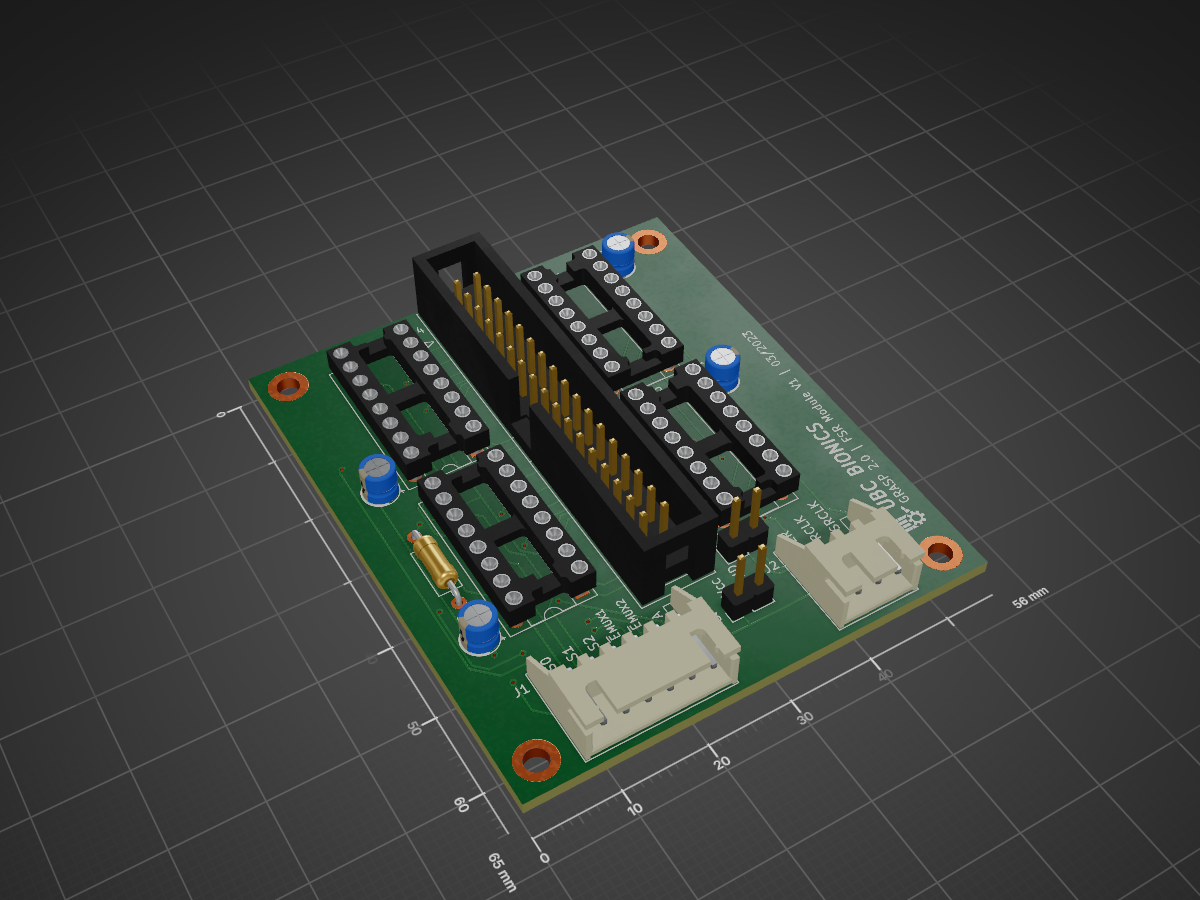
 BEARUBC/FSR_Mat_PCB2
This repository hosts the CAD files for the FSR PCB.
Tiaan fsr exp is an open-source printed circuit board by BEARUBC, from the BEARUBC/FSR_Mat_PCB repository on GitHub. It is a 2-layer board of 56 × 65 mm with 19 parts on 47 nets, routed with 295 tracks and 33 vias.
It is built around the 74HC4051 and 74HC595. Its parts include 5 connectors, 4 capacitors and 1 resistor.
**As of 2023-03-24, this README is outdated. Documentation for Tiaan's FSR is in progress.
These are the CAD files for the FSR printed circuit boards (PCB) using through-hole only components. This board is used for controlling a force sensitive resistor matrix, reading analog values from each cell.
This design is based off of Sensitronics' MatrixArray products which are comprised of a multitude of force sensing resistor elements arranged in a grid. Providing n-input multitouch + force sensing capabilities, MatrixArrays are the basis for musical instruments, PC input devices, and other innovative designs. If you have measured single-element FSRs by looking at the voltage across a divider, we're doing the same thing here.
But in this case, we're choosing the point to measure by powering a single drive column, enabling one mux channel so that the ADC sees a single row. In the next section, the Arduino code demonstrates a scan pattern to read all $\approx$ 160 elements in sequence.
Use a web browser to navigate to www.kicad.org the KiCad EDA website. Click the DOWNLOAD button on the KiCad home page. On the download page that opens, click the Windows button. Under Stable Release, click either Windows 64-bit or Windows 32-bit, depending on if you are going to install KiCad on a 32-bit or 64-bit version of the Windows operating system. Save the KiCad installation file. It may take a while to download, depending on your internet speed.
Ctrl + O) and navigate to this repositoryforce_sens_resistor.kicad_pro file*.sch file and begin to edit the boardArrange the hardware connections folling this schematic:
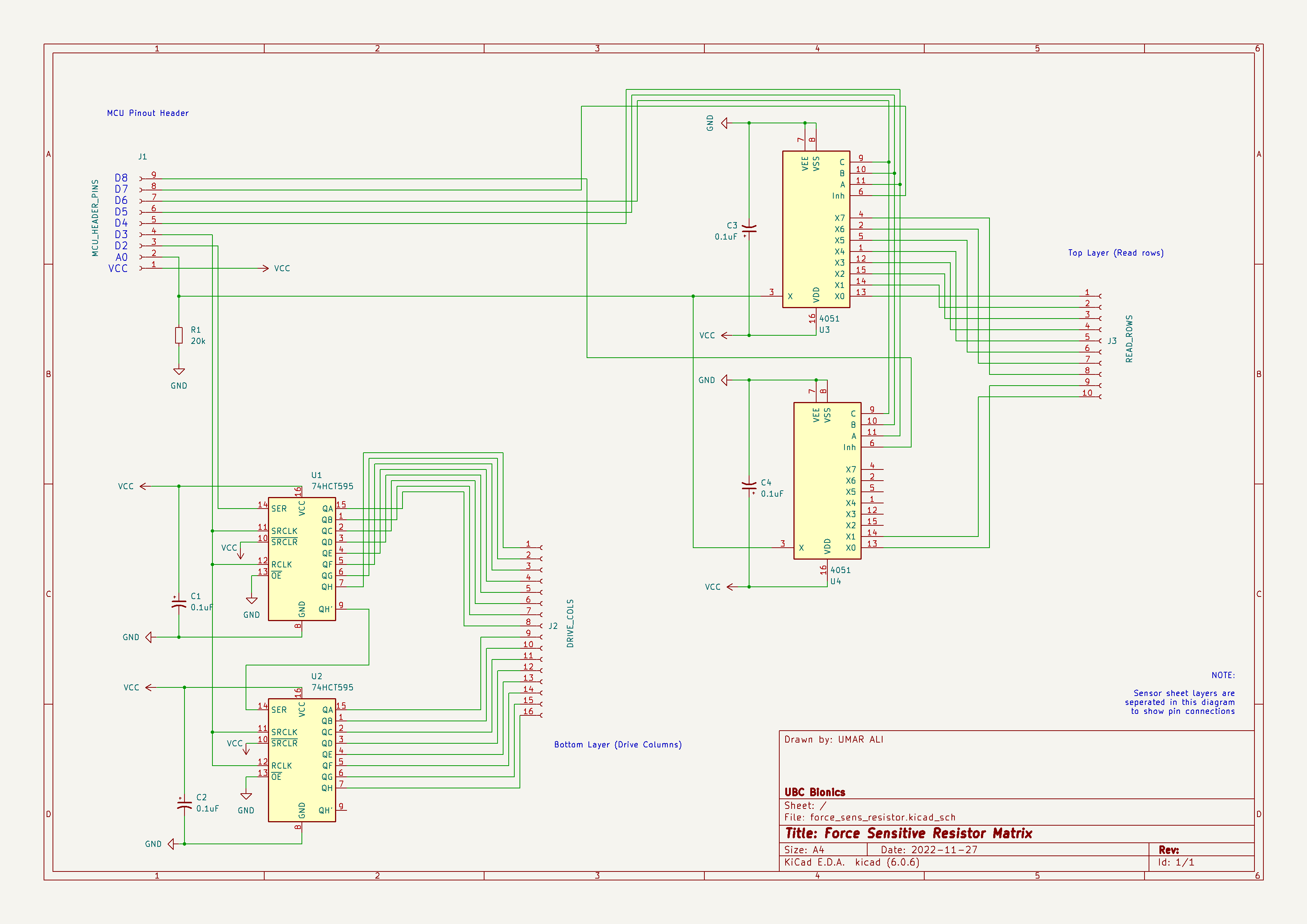
Now that the hardware's connected, it's time to write some code.
To read a single intersection, or "cell", of the MatrixArray, we need to perform the following sequence:
Simple enough, so from here, we will write a scan pattern to efficiently drive and read each cell of the Matrix. Recalling that we're calling shift register drive pins "rows" and multiplexed read pins "columns" in this example, we'll enable each column in order, and while each column is active, we'll drive each row high and take a reading.
// Constant definitions
...

void setup() {
  Serial.begin(BAUD_RATE);

  pinMode(PIN_ADC_INPUT, INPUT);
  pinMode(PIN_SHIFT_REGISTER_DATA, OUTPUT);
  pinMode(PIN_SHIFT_REGISTER_CLOCK, OUTPUT);
  pinMode(PIN_MUX_CHANNEL_0, OUTPUT);
  pinMode(PIN_MUX_CHANNEL_1, OUTPUT);
  pinMode(PIN_MUX_CHANNEL_2, OUTPUT);
  pinMode(PIN_MUX_INHIBIT_0, OUTPUT);
  pinMode(PIN_MUX_INHIBIT_1, OUTPUT);
}
void loop() {
  for(int i = 0; i < ROW_COUNT; i ++) {
    setRow(i);
    shiftColumn(true);
    shiftColumn(false);                         //with SR clks tied, latched outputs are one clock behind

    for(int j = 0; j < COLUMN_COUNT; j ++) {
      int raw_reading = analogRead(PIN_ADC_INPUT);
byte send_reading = (byte) (lowByte(raw_reading >> 2));Contributors names and contact info
Tiaan Boshoff Kyle Kochi Tiffany Prayitino Umar Ali
| Qty | Value | Footprint | References |
|---|---|---|---|
| 4 | 0.1uF | Capacitor_THT:CP_Radial_D4.0mm_P2.00mm | C1, C2, C3, C4 |
| 4 | MountingHole | MountingHole:MountingHole_2.7mm_M2.5_DIN965_Pad | H1, H2, H3, H4 |
| 2 | 74HC4051 | Package_DIP:DIP-16_W7.62mm_Socket | MUX1, MUX2 |
| 2 | 74HC595 | Package_DIP:DIP-16_W7.62mm_Socket | SR1, SR2 |
| 2 | Conn_01x02 | Connector_PinHeader_2.54mm:PinHeader_1x02_P2.54mm_Vertical | J3, J5 |
| 1 | 20k | Resistor_THT:R_Axial_DIN0207_L6.3mm_D2.5mm_P10.16mm_Horizontal | R1 |
| 1 | Conn_01x03 | Connector_JST:JST_XH_S3B-XH-A-1_1x03_P2.50mm_Horizontal | J2 |
| 1 | Conn_01x06 | Connector_JST:JST_XH_S6B-XH-A-1_1x06_P2.50mm_Horizontal | J1 |
| 1 | Conn_02x17_Odd_Even | Connector_IDC:IDC-Header_2x17_P2.54mm_Vertical | J4 |
| 1 | LOGO | LOGO | G*** |


mcbronkowitch/fireflow
FireFlow — a modulation-first ambient groovebox: the modulation system is the instrument, not a layer on top of it. Five independent lanes per part driving a synth, granular, wavetable, resonator or bucket-brigade deck.

ManuelArgibay/Industrial-I-O-Controller
Industrial 24V I/O controller featuring protected high-side and low-side outputs, multiplexed analog and digital inputs, and MCU-based control.


It measures 56 × 65 mm and has 2 copper layers, 1.6 mm thick.
19 parts, built around the 74HC4051 and 74HC595. The full list of its parts is on this page, with links to each part's symbol and footprint where PCBKit's library has them.
From the BEARUBC/FSR_Mat_PCB repository on GitHub, at the commit this page was made from: the board is tiaan_fsr_exp.kicad_pcb and its schematic force_sens_resistor.kicad_sch. PCBKit opens the board in the browser, with nothing to install.
Its repository states no licence, so its author keeps all rights: ask BEARUBC before reusing the design.