2 layers73.7 × 63.5 mm
Traffic light
BDeuDev/esp32-practice-c
This repository documents my hands-on journey into Embedded Systems and Firmware Engineering
9 parts
 BDeuDev/esp32-practice-c
This repository documents my hands-on journey into Embedded Systems and Firmware Engineering
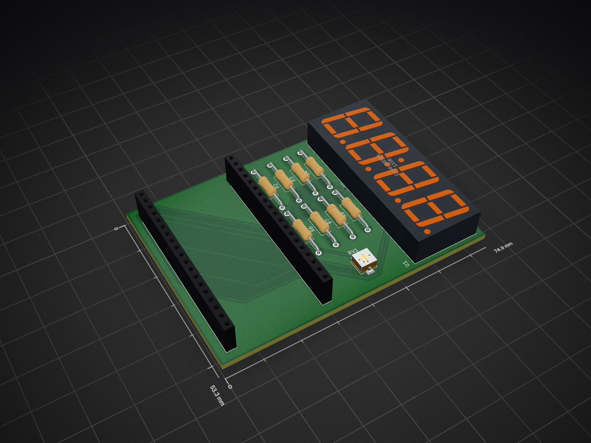
Adc potentiometer is an open-source printed circuit board by BDeuDev, from the BDeuDev/esp32-practice-c repository on GitHub. It is a 2-layer board of 74.9 × 53.3 mm with 12 parts on 44 nets, routed with 120 tracks and 5 vias.
Its parts include 8 resistors, 2 connectors and 1 IC.
This repository documents my hands-on journey into Embedded Systems and Firmware Engineering using the ESP32 and ESP-IDF with The C Programming Language.
The goal is to learn by building. Each project focuses on a specific concept, peripheral, or embedded programming technique while improving my understanding of electronics, real-time systems, hardware debugging, and firmware development.
Rather than creating production-ready applications, this repository serves as a collection of experiments, exercises, and practical projects that help me develop embedded engineering skills.
graph TD
    ROOT[ESP32 Learning Journey]

    ROOT --> BLINK[01_blink]
    ROOT --> TRAFFIC[02_traffic_light]
    ROOT --> BUTTON[03_button]
    ROOT --> PWM[04_pwm_led]
    ROOT --> ADC[05_adc_potentiometer]

    BLINK --> BLINK_README[README.md]
    BLINK --> BLINK_FW[firmware]
    BLINK --> BLINK_HW[hardware]

    TRAFFIC --> TRAFFIC_README[README.md]
    TRAFFIC --> TRAFFIC_FW[firmware]
    TRAFFIC --> TRAFFIC_HW[hardware]

    BUTTON --> BUTTON_README[README.md]
    BUTTON --> BUTTON_FW[firmware]
    BUTTON --> BUTTON_HW[hardware]

    PWM --> PWM_README[README.md]
    PWM --> PWM_FW[firmware]
PWM --> PWM_HW[hardware]| Project | Concept |
|---|---|
| 01 - Blink | Basic GPIO output and ESP-IDF project structure |
| 02 - Traffic Light | Multiple GPIO outputs and timing control |
| 03 - Button | GPIO input, ISR and IRAM attr |
| 04 - PWM LED | PWM (Pulse Width Modulation) |
| 05 - ADC Potentiometer | ADC (Analog-to-Digital Conversion) |
I created this repository to:
| Qty | Value | Footprint | References |
|---|---|---|---|
| 8 | 220 | Resistor_THT:R_Axial_DIN0207_L6.3mm_D2.5mm_P15.24mm_Horizontal | R1, R2, R3, R4, R5, R6, R7, R8 |
| 2 | Conn_01x19_Socket | Connector_PinSocket_2.54mm:PinSocket_1x19_P2.54mm_Vertical | J1, J2 |
| 1 | 10k | Potentiometer_SMD:Potentiometer_Bourns_3314G_Vertical | RV1 |
| 1 | CA56-12EWA | Display_7Segment:CA56-12SEKWA | U1 |
BDeuDev/esp32-practice-c
This repository documents my hands-on journey into Embedded Systems and Firmware Engineering

BDeuDev/esp32-practice-c
This repository documents my hands-on journey into Embedded Systems and Firmware Engineering

BDeuDev/esp32-practice-c
This repository documents my hands-on journey into Embedded Systems and Firmware Engineering

github-linguist/linguist
Language Savant. If your repository's language is being reported incorrectly, send us a pull request!


google/mozc-devices
Circuit diagrams and firmware source code for Gboard DIY keyboards


hackclub/OnBoard
💡 Join 1,000 teenagers and make your first PCB with a $100 grant!

VoronDesign/Voron-Tap
Tap is a nozzle-based z-probe for the V2 and Trident printer designs. The entire toolhead moves to trigger an optical switch. Tap offers many advantages:

stacksmashing/pico-tpmsniffer
A simple, very experimental TPM sniffer for LPC bus
It measures 74.9 × 53.3 mm and has 2 copper layers, 1.6 mm thick.
12 parts. The full list of its parts is on this page, with links to each part's symbol and footprint where PCBKit's library has them.
From the BDeuDev/esp32-practice-c repository on GitHub, at the commit this page was made from: the board is 05_adc_potentiometer/hardware/adc_potentiometer.kicad_pcb and its schematic 01_blink/hardware/blink.kicad_sch. PCBKit opens the board in the browser, with nothing to install.
Its repository states no licence, so its author keeps all rights: ask BDeuDev before reusing the design.