Skip to the content
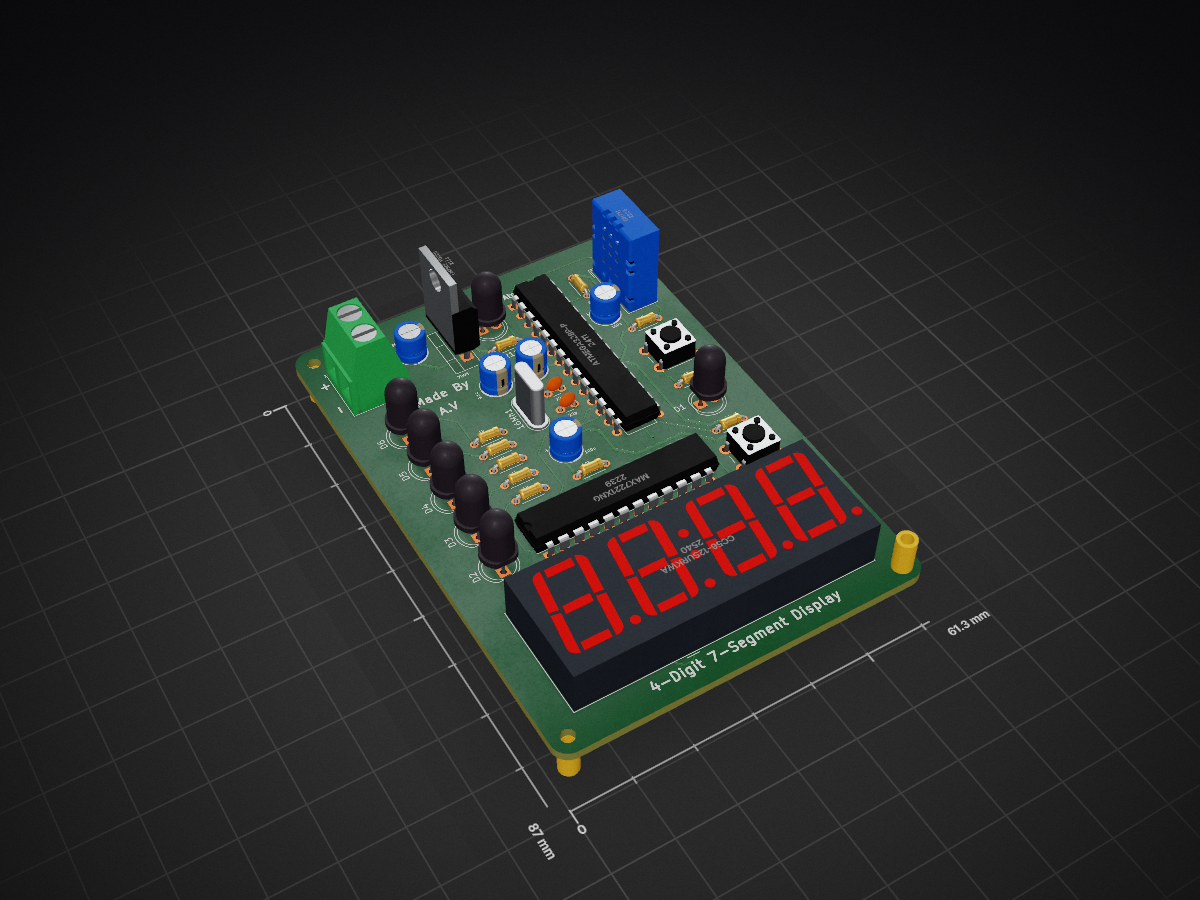
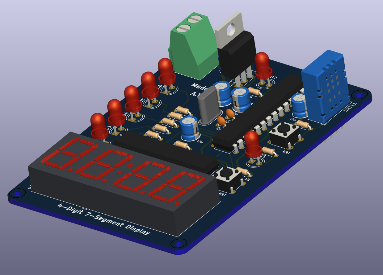
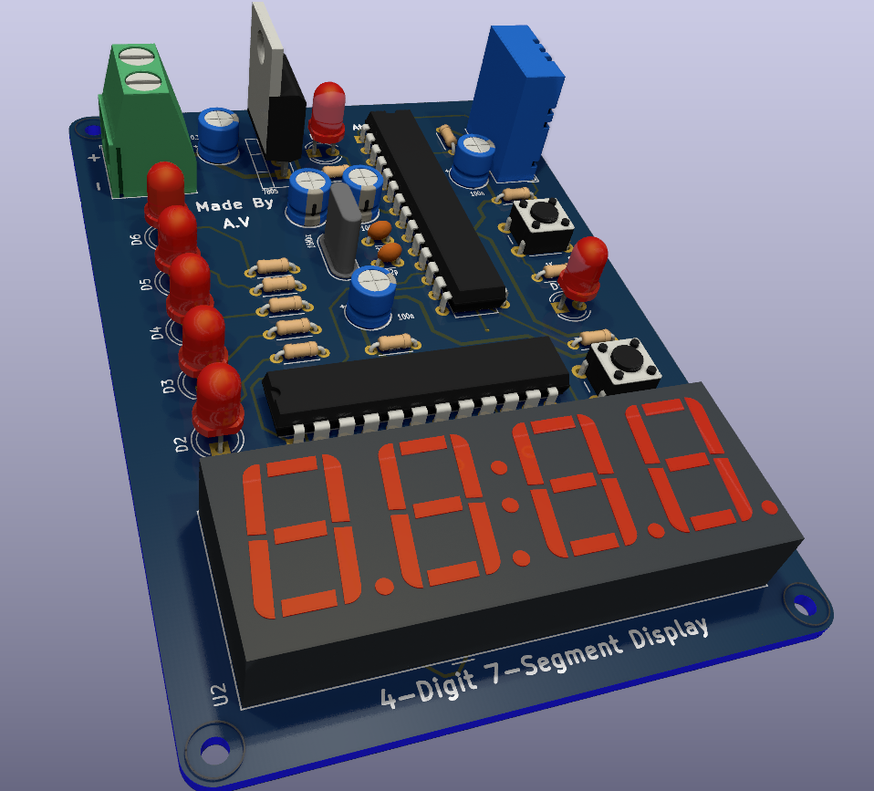
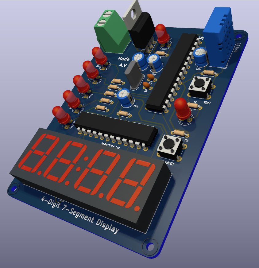
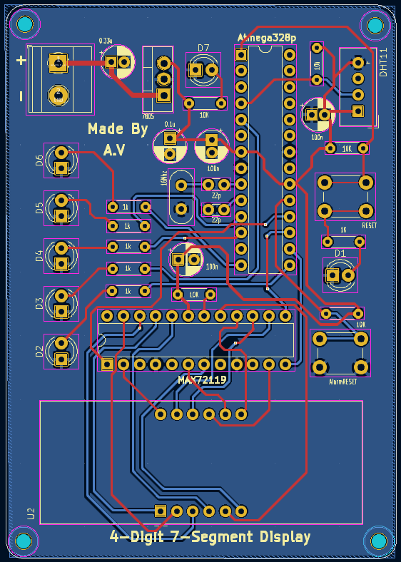
2 layers61.3 × 87 mmTemp, the printed circuit board in 3D

This project is a temperature display and alarm system designed for educational purposes as part of the IA 2209 - Microcontroller Laboratory course.

Size
61.3 × 87 mm
Copper layers
2
Thickness
1.6 mm
Parts
38
Nets
55
Pads
137
Tracks, vias
256, 6
Pours
1
Routed
Yes
KiCad
KiCad 8.0 (file 20240108)
Created
30 May 2024
Updated
21 Nov 2024

Overview

Temp is an open-source printed circuit board by AvishkaVishwa, from the AvishkaVishwa/Microcontroller-Design-Project-Temperature-Monitoring-System repository on GitHub. It is a 2-layer board of 61.3 × 87 mm with 38 parts on 55 nets, routed with 256 tracks and 6 vias.

It is built around the ATMEGA328P-PU, DHT11 and CC56-12SURKWA. Its parts include 11 resistors, 7 capacitors, 7 diodes, 5 ICs and 1 connector. It belongs with the lEDs and displays boards and the AVR (ATmega, ATtiny) boards of this library.

Main components

3

README

README.md

Microcontroller-Design-Project-

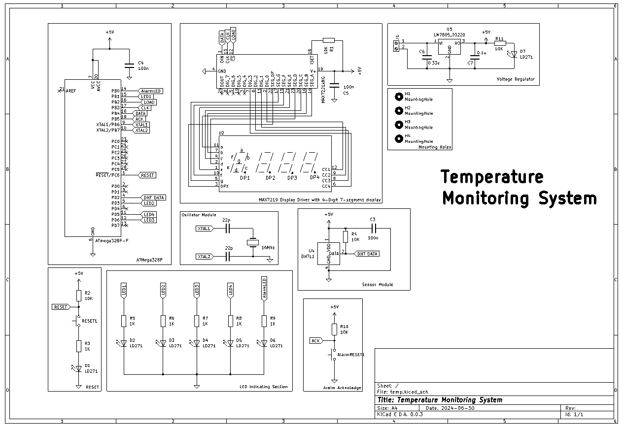
This project is part of the IA 2209 - Microcontroller Laboratory course. It involves creating a microcontroller-based temperature monitoring system with various features including temperature display, alarm, and range indication using LEDs.

Features

  • Temperature Display: Displays the current temperature on a 7-segment display with the ability to switch between Celsius and Fahrenheit.
  • Temperature Alarm: An alarm system that triggers when the temperature exceeds 40°C.
  • Temperature Range Indication: LEDs indicate different temperature ranges with varying brightness.
  • Mode Switching: Toggle between displaying temperature (Celsius and Fahrenheit) and temperature range.

Components

  • ATmega328P Microcontroller
  • MAX7219CNG Display driver
  • 4-Digit 7-segment displays
  • LEDs
  • Push buttons
  • Resistors, capacitors, and other supporting components

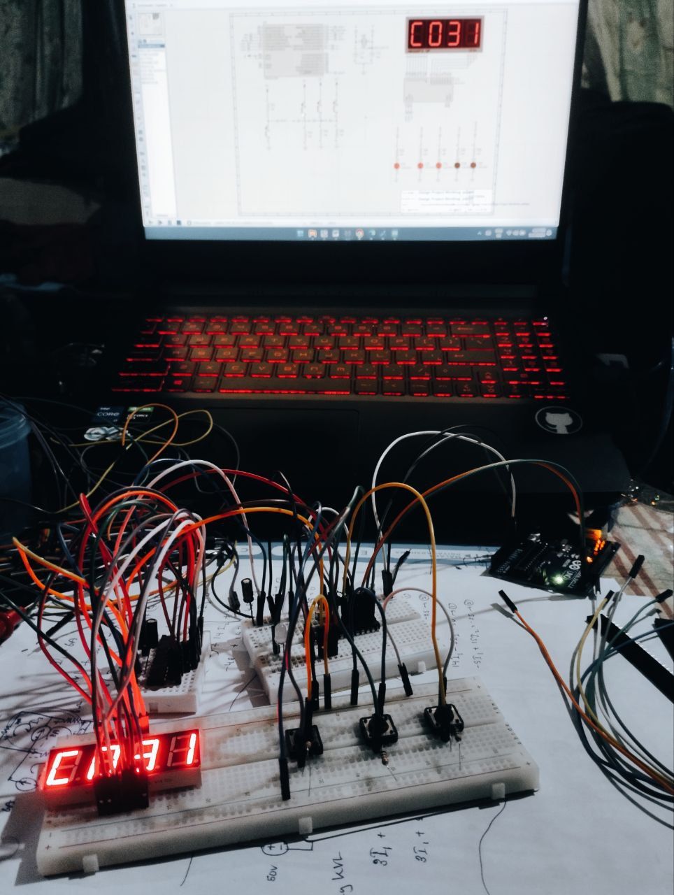
Simulation on Proteus

https://github.com/user-attachments/assets/188e2a22-0e74-4096-baf8-a73c14bb029d

Hardware Testing

https://github.com/user-attachments/assets/ba68c1e6-b078-402f-8ae6-b2f3dc63eebe

Usage

  1. Compile and Upload Code: Compile the provided C/C++ code and upload it to the ATmega328P microcontroller.
  2. Hardware Setup: Connect the hardware components as per the circuit diagram provided in hardware/circuit_diagram.png.
  3. Operating the System:
    • Use the increment and decrement buttons to adjust the temperature.
    • The current temperature is displayed on the 7-segment display.
    • The alarm LED blinks if the temperature exceeds 40°C and can be acknowledged with the acknowledgment button.
    • LEDs indicate the current temperature range.

Parts

38
QtyValueFootprintReferences
7LD271LED_THT:LED_D5.0mm_IRGreyD1, D2, D3, D4, D5, D6, D7
61KResistor_THT:R_Axial_DIN0204_L3.6mm_D1.6mm_P5.08mm_HorizontalR3, R5, R6, R7, R8, R9
510KResistor_THT:R_Axial_DIN0204_L3.6mm_D1.6mm_P5.08mm_HorizontalR1, R2, R4, R10, R11
4MountingHoleMountingHole:MountingHole_2.2mm_M2H1, H2, H3, H4
2100nCapacitor_THT:CP_Radial_D5.0mm_P2.00mmC3, C4
222pCapacitor_THT:C_Disc_D3.0mm_W1.6mm_P2.50mmC1, C2
2SW_PushButton_Switch_THT:SW_PUSH_6mmAlarmRESET1, RESET1
10.1uCapacitor_THT:CP_Radial_D5.0mm_P2.50mmC7
10.33uCapacitor_THT:CP_Radial_D5.0mm_P2.00mmC6
1100nCapacitor_THT:CP_Radial_D5.0mm_P2.50mmC5
116MhzCrystal:Crystal_HC52-8mm_Vertical16Mh1
1ATmega328P-PPackage_DIP:DIP-28_W7.62mmU1
1CC56-12SURKWADisplay_7Segment:CA56-12SURKWAU2
1DHT11Sensor:Aosong_DHT11_5.5x12.0_P2.54mmU4
1LM7805_TO220Package_TO_SOT_THT:TO-220-3_VerticalU5
1MAX7221xNGPackage_DIP:DIP-24_W7.62mmU3
1Screw_Terminal_01x02TerminalBlock_Phoenix:TerminalBlock_Phoenix_MKDS-1,5-2-5.08_1x02_P5.08mm_HorizontalJ1

More from AvishkaVishwa/Microcontroller-Design-Project-Temperature-Monitoring-System

1
  • 2 layers101.5 × 53 mmTemp, the printed circuit board in 3D

    Temp

    AvishkaVishwa/Microcontroller-Design-Project-Temperature-Monitoring-System

    This project is a temperature display and alarm system designed for educational purposes as part of the IA 2209 - Microcontroller Laboratory course.

    29 parts4

Similar boards

  • 2 layers68 × 110 mmMultimeter, the printed circuit board in 3D

    Multimeter

    schuyler4/Multimeter

    My multimeter design.

    133 parts3MIT
  • 2 layers90 × 81 mmSTM32-Environmental Monitor PCB, the printed circuit board in 3D

    STM32-Environmental Monitor PCB

    angelozyh/STM32-Environmental-Monitor-PCB

    A custom 2-layer PCB designed in KiCad for an STM32-based environmental monitoring system. The board integrates an STM32 NUCLEO-F303K8, BME280 environmental sensor, dual SN74HC595 shift registers, a 4-digit 7-segment…

    29 parts1
  • 2 layers96.5 × 60 mmPocket sunrise, the printed circuit board in 3D

    Pocket sunrise

    Yasu31/pocket-sunrise

    DIY wake-up light alarm clock

    30 parts1MIT
  • 2 layers85 × 74 mmFuente de voltaje, the printed circuit board in 3D

    Fuente de voltaje

    aaronledesma/TCI-display-voltage-CAD

    Easy EDA design PCB

    21 parts
  • 2 layers100 × 100 mmCan ssr, the printed circuit board in 3D

    Can ssr

    czalinski/ThlHats

    Test devices with Raspberry PI HAT form factor

    201 partsMIT
  • 2 layers66 × 66 mmAttiny85 7seg, the printed circuit board in 3D

    Attiny85 7seg

    Spac3y/seg7-85

    A 4-digit 7-segment display driven by an ATtiny85, scrolling a text message across the display.

    31 parts
  • 4 layers293.6 × 143.3 mmSchema and PCB, the printed circuit board in 3D

    Schema and PCB

    SVIELCOM/MWE_Schema_and_PCB

    Схема и плата ШВУ-2

    251 parts
  • 2 layers76.2 × 165.1 mmMicrowave, the printed circuit board in 3D

    Microwave

    Tektronica/embedded

    Monorepo - home to embedded projects

    67 parts

Questions

How big is the Temp PCB?

It measures 61.3 × 87 mm and has 2 copper layers, 1.6 mm thick.

What parts does the Temp use?

38 parts, built around the ATMEGA328P-PU, DHT11 and CC56-12SURKWA. The full list of its parts is on this page, with links to each part's symbol and footprint where PCBKit's library has them.

Where can I download the Temp KiCad files?

From the AvishkaVishwa/Microcontroller-Design-Project-Temperature-Monitoring-System repository on GitHub, at the commit this page was made from: the board is PCB Design Using KiCAD/temp.kicad_pcb and its schematic PCB Design Using KiCAD/temp.kicad_sch. PCBKit opens the board in the browser, with nothing to install.

Can I use the Temp design in my own project?

Its repository states no licence, so its author keeps all rights: ask AvishkaVishwa before reusing the design.