Skip to the content
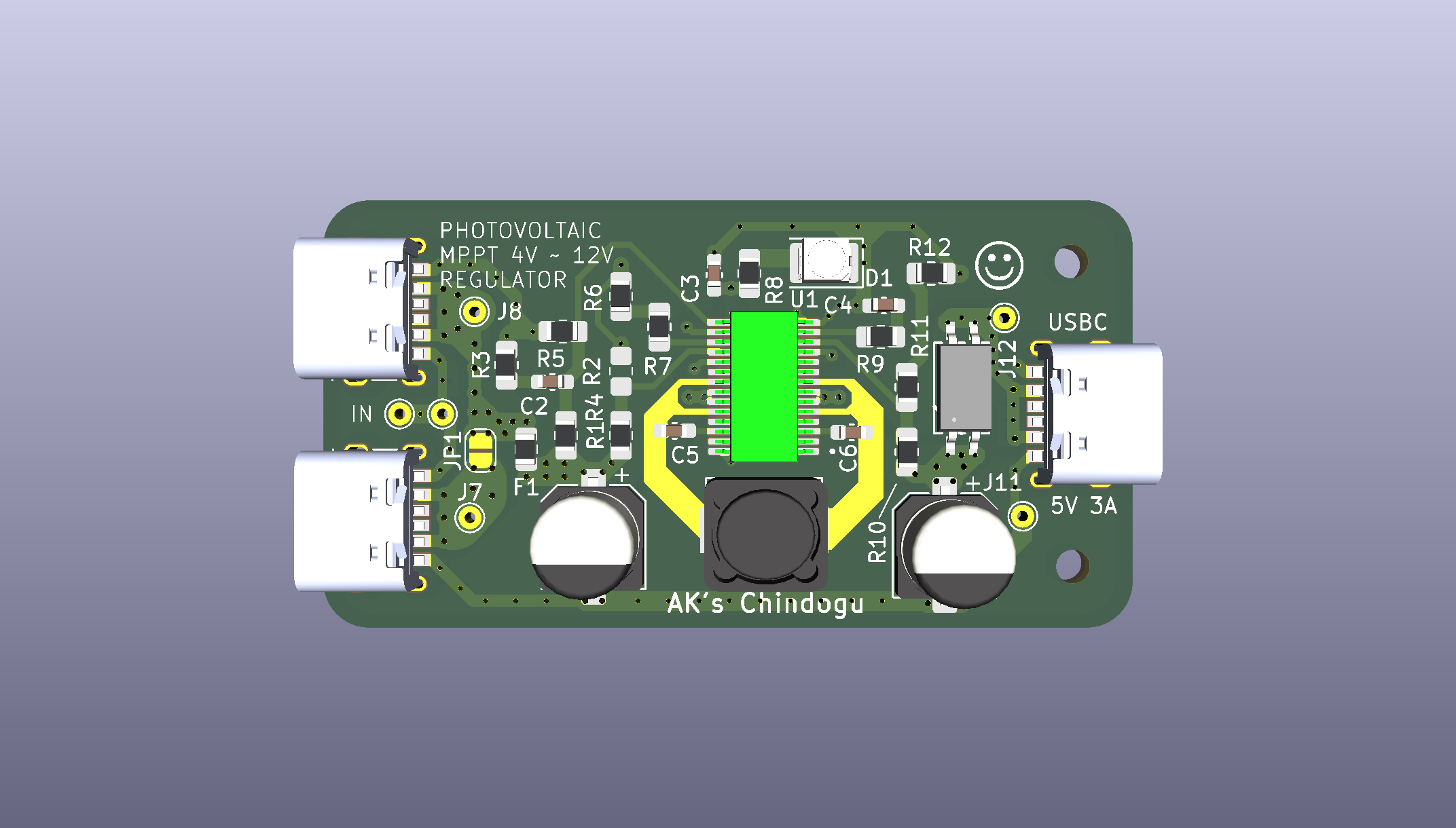
2 layers53 × 28 mmSolarRegulatorFun, the printed circuit board in 3D

SolarRegulatorFun

Asvoria/SolarRegulatorFun

Just a tiny project.

Size
53 × 28 mm
Copper layers
2
Thickness
1.6 mm
Parts
36
Nets
43
Pads
117
Tracks, vias
544, 119
Pours
5
Routed
Yes
KiCad
KiCad 10.0 (file 20260206)
Created
11 Jul 2026
Updated
4 Aug 2026

Overview

SolarRegulatorFun is an open-source printed circuit board by Asvoria, from the Asvoria/SolarRegulatorFun repository on GitHub, published under the GPL-3.0 licence. It is a 2-layer board of 53 × 28 mm with 36 parts on 43 nets, routed with 544 tracks and 119 vias.

It is built around the MFU0805FF03150P500 and SA77SB0. Its parts include 12 resistors, 11 connectors, 7 capacitors, 2 fuses and 1 IC.

Main components

2

README

README.md

Simple Solar-Cell 5V Regulator (SolarRegulatorFun)

View PS: This README.md content is generated by GitHub-Copilot.

This repository contains a small educational project that demonstrates a photovoltaic (solar panel) to 5 V regulated output using an LTC3119 switching regulator (LTC3119FB device model and library included). The project includes schematic and PCB files (KiCad), LTspice simulation files so you can simulate the regulator behavior, and supporting library PDFs and notes.

This repo is aimed at students and hobbyists who want a compact, practical example of using a switching regulator to make a stable 5 V supply from a solar panel while preserving good efficiency.

What's new / highlights

  • Design updated to use the Linear Technology/Analog Devices LTC3119 switching regulator (LTC3119FB). The schematic and LTspice model in this repo use the LTC3119 symbol (U1 in the LTspice schematic).
  • An LTspice schematic (SolarRegulatorFun/SolarRegulatorFun.asc) with simulation parameters is included so users can run transient simulations and inspect startup and steady-state behavior before building.
  • KiCad project (schematic and PCB) is included (SolarRegulatorFun/SolarRegulatorFun.kicad_sch and SolarRegulatorFun.kicad_pcb).
  • Component library PDFs / datasheets used in the project are included in SolarRegulatorFun/CustomKiCadLib/ (for example: 3119fb.pdf).

Repository layout (important files/folders)

  • SolarRegulatorFun/
    • SolarRegulatorFun.kicad_sch - KiCad schematic
    • SolarRegulatorFun.kicad_pcb - KiCad PCB layout
    • SolarRegulatorFun.asc - LTspice schematic (simulation)
    • CustomKiCadLib/ - PDFs and library references used by the KiCad project
      • 3119fb.pdf - LTC3119 datasheet / app note used for the design
      • ujc-hp2-3-smt-tr.pdf - footprint/part reference PDFs
  • README.md - this file
  • LICENSE - project license

Quick start — view and simulate

  1. View schematic / PCB

    • Open SolarRegulatorFun/SolarRegulatorFun.kicad_sch and SolarRegulatorFun/SolarRegulatorFun.kicad_pcb with KiCad (recommended KiCad v6 or later). The exact KiCad version used to create the files is indicated in the KiCad file headers; use a recent KiCad release for best compatibility.
    • The CustomKiCadLib folder contains PDFs and footprints used by the project — consult them if KiCad prompts for missing library items.
  2. Simulate with LTspice

    • Install LTspice (Analog Devices LTspice XVII or later).
    • Open SolarRegulatorFun/SolarRegulatorFun.asc with LTspice.
    • The included LTspice schematic contains the LTC3119 symbol (U1) and the supporting components. Simulation directives intended for transient behavior are included as comments in the schematic; to run the recommended simulation:
      • Add or enable the following directives in LTspice:
        • .tran 5m startup ; run a 5 millisecond transient simulation to capture startup
        • .softstart .1 ; (optional) cause the model to perform internal soft-start at 10% of nominal time — helps observe startup behavior
      • Note: In the included .asc these directives are shown in the schematic text (you may need to remove a leading "!" if they appear commented-out in the schematic). After enabling the directives, run the simulator (Running -> Simulate).
    • Inspect node voltages, inductor currents, and output ripple. The Rload element in the schematic can be adjusted to test different load conditions (the included config uses Rload=1Ω as a test load). Component values (inductor, capacitors, resistors) are set in the schematic — open the .asc file to see exact values.

Design notes and BOM highlights

  • Regulator IC: LTC3119 (LTC3119FB package referenced in CustomKiCadLib/3119fb.pdf)
  • Key passive examples from the LTspice schematic (see SolarRegulatorFun.asc for exact values):
    • Inductor L1 ≈ 2.7 µH (value shown in the LTspice schematic)
    • Bulk output cap C3 ≈ 220 µF (electrolytic/low-ESR recommended)
    • Softstart and compensation components are present in the LTspice schematic; follow LTC3119 datasheet recommendations when selecting values for a production design.
  • Always cross-check footprints and pad sizes in the KiCad PCB with the manufacturer mechanical drawings in the CustomKiCadLib folder before ordering boards.

Simulate-first workflow (recommended)

  1. Open and simulate SolarRegulatorFun.asc in LTspice; adjust the solar panel input (the V1 source) to match the panel expected IV curve or use a PWL source included in the schematic.
  2. Validate startup, steady-state output voltage (5 V target), efficiency under expected load, and thermal behavior (where possible) in simulation.
  3. Tune component values and compensation networks in the schematic until the regulator is stable with minimal overshoot and acceptable ripple.
  4. Update KiCad schematic and PCB, then generate Gerbers for fabrication.

Contributing and notes

  • This repo is intended as an educational, refresh project. Contributions, suggestions, or corrections are welcome — open an issue or submit a pull request.
  • If you build and test this circuit, please share measured results (efficiency, output ripple, behavior under varying panel illumination) so future readers can benefit.

License See LICENSE in the project root.

Thanks for checking out the project! If anything is unclear or you want the README to include additional sections (assembly guide, test procedures, measured data tables), tell me which sections to add and they will be included.

Parts

36
QtyValueFootprintReferences
6Conn_01x01_PinTestPoint:TestPoint_THTPad_D1.5mm_Drill0.7mmJ5, J6, J7, J8, J11, J12
5100kResistor_SMD:R_0805_2012Metric_Pad1.20x1.40mm_HandSolderR1, R3, R5, R6, R11
3USBCCustom:CUI_UJC-HP2-3-SMT-TRJ1, J2, J3
20.1uCapacitor_SMD:C_0603_1608Metric_Pad1.08x0.95mm_HandSolderC5, C6
2100uCapacitor_SMD:CP_Elec_6.3x5.7C1, C7
2MountingScrewMountingHole:MountingHole_2.2mm_M2J9, J10
11nCapacitor_SMD:C_0603_1608Metric_Pad1.08x0.95mm_HandSolderC2
12.7uInductor_SMD:L_Neosid_SM-PIC0612HL1
1210Resistor_SMD:R_0805_2012Metric_Pad1.20x1.40mm_HandSolderR8
12kResistor_SMD:R_0805_2012Metric_Pad1.20x1.40mm_HandSolderR12
1360kResistor_SMD:R_0805_2012Metric_Pad1.20x1.40mm_HandSolderR4
14.7uCapacitor_SMD:C_0603_1608Metric_Pad1.08x0.95mm_HandSolderC3
1536kResistor_SMD:R_0805_2012Metric_Pad1.20x1.40mm_HandSolderR10
15kResistor_SMD:R_0805_2012Metric_Pad1.20x1.40mm_HandSolderR7
1680pCapacitor_SMD:C_0603_1608Metric_Pad1.08x0.95mm_HandSolderC4
172kResistor_SMD:R_0805_2012Metric_Pad1.20x1.40mm_HandSolderR2
178.7kResistor_SMD:R_0805_2012Metric_Pad1.20x1.40mm_HandSolderR9
1Jumper_2_OpenJumper:SolderJumper-2_P1.3mm_Open_RoundedPad1.0x1.5mmJP1
1LEDLED_SMD:LED_PLCC-2_3.4x3.0mm_KAD1
1LTC3119EFE_PBFCustom:SOP65P640X120-29NU1
1MFU0805FF03150P500Fuse:Fuse_0805_2012MetricF1
1SA77SB0Custom:FUSE_SA77SB0_BRNF2

Similar boards

  • 2 layers65 × 30 mmRgb to hdmi, the printed circuit board in 3D

    Rgb to hdmi

    hoglet67/RGBtoHDMI

    Bare-metal Raspberry Pi project that provides pixel-perfect sampling of Retro Computer RGB/YUV video and conversion to HDMI

    36 parts1kGPL-3.0
  • 2 layers55 × 70 mmArduino v1, the printed circuit board in 3D

    Arduino v1

    hackclub/OnBoard

    💡 Join 1,000 teenagers and make your first PCB with a $100 grant!

    36 parts915
  • 2 layers50.4 × 24.8 mmLEDboardRev3, the printed circuit board in 3D

    LEDboardRev3

    Architeuthis-Flux/Jumperless

    A jumperless breadboard

    36 parts914
  • 2 layers45.7 × 31.8 mmLEDx16 board, the printed circuit board in 3D

    LEDx16 board

    tardate/LittleArduinoProjects

    a collection of "Little Electronic & Arduino Projects", most involving electronics or an Arduino in one way or another!

    36 parts803MIT
  • 2 layers32 × 24 mmEsp onelayer3, the printed circuit board in 3D

    Esp onelayer3

    cnlohr/colorchord

    Chromatic Sound to Light Conversion System

    36 parts712
  • 2 layers69 × 53.8 mmTUSS4470 shield, the printed circuit board in 3D

    TUSS4470 shield

    Neumi/open_echo

    Open Source echo sounder / depth sounder / SONAR for bathymetry and research. Arduino based and compatible.

    36 parts530
  • 2 layers99.1 × 53.3 mmABSIS Mega, the printed circuit board in 3D

    ABSIS Mega

    jrsteensen/OpenHornet

    OpenHornet 1:1 F/A-18C Simulator Repository

    36 parts431
  • 2 layers16.1 × 119 mmConnectorL, the printed circuit board in 3D

    ConnectorL

    thpoll83/PolyKybd

    PolyKybd

    36 parts411CERN-OHL-W-2.0

Questions

How big is the SolarRegulatorFun PCB?

It measures 53 × 28 mm and has 2 copper layers, 1.6 mm thick.

What parts does the SolarRegulatorFun use?

36 parts, built around the MFU0805FF03150P500 and SA77SB0. The full list of its parts is on this page, with links to each part's symbol and footprint where PCBKit's library has them.

Where can I download the SolarRegulatorFun KiCad files?

From the Asvoria/SolarRegulatorFun repository on GitHub, at the commit this page was made from: the board is SolarRegulatorFun/SolarRegulatorFun.kicad_pcb and its schematic SolarRegulatorFun/SolarRegulatorFun.kicad_sch. PCBKit opens the board in the browser, with nothing to install.

Can I use the SolarRegulatorFun design in my own project?

Its repository publishes it under the GPL-3.0 licence: you may reuse it on that licence's terms (keep the author's notice, and for a copyleft licence share your changes alike).