2 layers132.1 × 45.7 mm
IPoS
peterheinrich/InternetOverSpaghetti
Transmitting IP packages over a pair of spaghetti thus demonstrating how media independent IP really is.
42 parts342
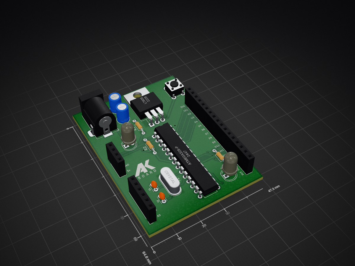
 ArunkumarAK001/ATmega328P-Development-Board
Double-layer ATmega328P Development Board designed using KiCad.
ATmega38p pu board is an open-source printed circuit board by ArunkumarAK001, from the ArunkumarAK001/ATmega328P-Development-Board repository on GitHub. It is a 2-layer board of 47.3 × 64.6 mm with 18 parts on 29 nets, routed with 222 tracks and 8 vias.
It is built around the ATMEGA328-PU and L7805. Its parts include 4 capacitors, 4 connectors, 3 resistors, 2 ICs and 2 diodes. It belongs with the AVR (ATmega, ATtiny) boards of this library.


A minimal ATmega-based board designed from scratch, functionally compatible with Arduino. Designed in KiCad, taken from breadboard prototype to a finished PCB.
This board runs the same way an Arduino Uno/Nano does, but built as a custom PCB. It does not include an onboard USB-to-serial chip — programming is done externally via a USB-to-TTL serial adapter (e.g. CP2102 / CH340 / FTDI).


| Component | Value/Part | Qty |
|---|---|---|
| ATmega328P | - | 1 |
| Crystal | 16MHz | 1 |
| Capacitor | 22pF | 2 |
| Capacitor | 100nF | 2 |
| Resistor | 10k (reset pull-up) | 1 |
| Voltage regulator | Lm317 | 1 |
| Reset Push Button | - | 1 |
| LED | 3v | 2 |
/hardware — KiCad project files (schematic + PCB layout)/gerbers — Manufacturing files (Gerbers, drill files)/images — Breadboard, PCB, and schematic photosDuring this process I learnt about the actual PCB design, from the bread connection to Real PCB. I faced many challeges during this process I rectified all and I Finally built the development board.
| Qty | Value | Footprint | References |
|---|---|---|---|
| 3 | R | Resistor_THT:R_Axial_DIN0204_L3.6mm_D1.6mm_P7.62mm_Horizontal | R1, R2, R3 |
| 2 | C | Capacitor_THT:C_Disc_D3.0mm_W2.0mm_P2.50mm | C1, C2 |
| 2 | C | Capacitor_THT:C_Radial_D5.0mm_H7.0mm_P2.00mm | C3, C4 |
| 2 | LED | LED_THT:LED_D5.0mm_Clear | D1, D2 |
| 1 | ATmega328-P | Package_DIP:DIP-28_W7.62mm | U2 |
| 1 | Barrel_Jack_MountingPin | Connector_BarrelJack:BarrelJack_Horizontal | J1 |
| 1 | Conn_01x04_Socket | Connector_PinSocket_2.54mm:PinSocket_1x04_P2.54mm_Vertical | J4 |
| 1 | Conn_01x06_Socket | Connector_PinSocket_2.54mm:PinSocket_1x06_P2.54mm_Vertical | J2 |
| 1 | Conn_01x17_Socket | Connector_PinSocket_2.54mm:PinSocket_1x17_P2.54mm_Vertical | J3 |
| 1 | Crystal | Crystal:Crystal_HC49-4H_Vertical | Y1 |
| 1 | L7805 | Package_TO_SOT_THT:TO-220-3_Horizontal_TabDown | U1 |
| 1 | LOGO | LOGO | G |
| 1 | SW_Push | Button_Switch_THT:SW_PUSH_6mm | SW1 |
peterheinrich/InternetOverSpaghetti
Transmitting IP packages over a pair of spaghetti thus demonstrating how media independent IP really is.


avrovulcanxh607/teletext-decoder
This repo is an attempt to open-source my teletext decoder.


bmatthieu3/clockdivider
A simple clock divider module made with an Atmega328p

captainchapster/Entropy32
A dedicated Bitcoin seed phrase generator that uses radioactive decay as an entropy source. Completely open source and designed to be simple, auditable, and built by anyone with readily available components.

dwkennedy/ballooning
Mutli-function balloon related project (variometer, balloon cut-down, let down reel, tracking)

KaburaJ/Dynamic-Speed-Governor
This repository contains the workflow of a dynamic speed governor. Designed to change as per a location's speed limit, this dynamic speed governor is highly applicable in school zones, hospitals and black spots among…
It measures 47.3 × 64.6 mm and has 2 copper layers, 1.6 mm thick.
18 parts, built around the ATMEGA328-PU and L7805. The full list of its parts is on this page, with links to each part's symbol and footprint where PCBKit's library has them.
From the ArunkumarAK001/ATmega328P-Development-Board repository on GitHub, at the commit this page was made from: the board is Hardware/ATmega38p-pu_board.kicad_pcb. PCBKit opens the board in the browser, with nothing to install.
Its repository states no licence, so its author keeps all rights: ask ArunkumarAK001 before reusing the design.