
2 layers70.5 × 99 mm

 Angelussss/Ducker-Charger20
an open source custom power bank
Ducker Charger is an open-source printed circuit board by Angelussss, from the Angelussss/Ducker-Charger repository on GitHub. It is a 4-layer board of 66.4 × 163.6 mm with 278 parts on 231 nets, routed with 2,195 tracks and 876 vias.
It is built around the TPS54302, BSC040N08NS5 and AO3400A, with the AO4407A, TYPE-C-31-M-12 and USBLC6-4SC6 among its other parts. Its parts include 86 capacitors, 68 resistors, 14 transistors, 6 inductors and 5 diodes. It belongs with the power boards of this library.


A fully custom, open-source smart power bank, designed from scratch.
4S3P Li-Ion pack · bidirectional USB-PD · bench-supply output · TFT telemetry UI



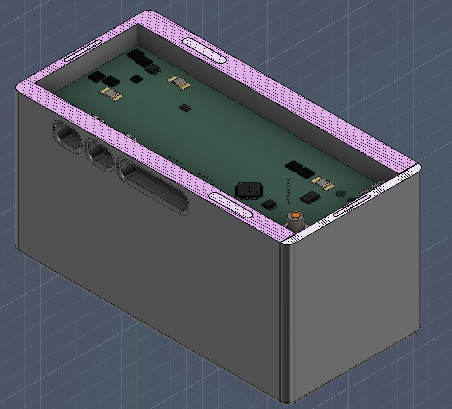 |  |
| Enclosure (prototype 3, lid off) | Live telemetry UI |
[!WARNING] Work in progress: the design is not yet validated. This project involves Li-Ion batteries, which can overheat, catch fire, or explode if mishandled. Take any information here at your own risk and read the safety note below.
Hardware
PCB/)Software
arm-none-eabi-gcc: the firmware builds via the CubeMX-generated Makefile in firmware/cubeMX/, no IDE requiredst-flash (stlink-tools) or STM32CubeProgrammer, to flash over SWDgcc + SDL2: only needed for firmware/emulator/ and firmware/interface-tester/ (no hardware required to run these)cubeMX.iocDistributed design: cell safety, power conversion, PD negotiation and gauging
each live in a dedicated IC; the STM32 supervises, aggregates telemetry and
drives the UI. Block diagram in PCB/README.md.
| Subsystem | Part | Role |
|---|---|---|
| Safety / Protection | TI BQ77915 + N-ch MOSFETs | Autonomous, software-independent cell OV/UV/SC/OC cutoff (4S, always-on) |
| Charger | TI BQ25713 | Buck-boost NVDC battery charger (driven by the TPS25750 on a private I²C bus) |
| Main USB-C PD | TI TPS25750 | Primary PD port controller; patch bundle streamed by the MCU at every boot |
| Aux USB-C PD | Infineon CYPD3175 (CCG3PA) | Secondary PD port negotiation (replaced the EOL STUSB4710) |
| Aux programmable rail | ST STPD01 | I²C-programmable supply for the secondary USB-C / lab output |
| Fuel gauge | TI BQ34Z100-R2 | Impedance Track™ State-of-Charge / Time-to-Empty |
| Telemetry | TI INA3221 | 3-channel voltage/current monitoring |
| Step-down | TI TPS54302 / TPS54202 | Auxiliary rails |
| ESD / I²C isolation | USBLC6, ISO1540 | Port ESD protection, isolated I²C to the battery-referenced gauge |
| Host | STM32F401RBT6 | I²C master, power-state FSM, thermal manager, HMI / supervisor |
| Path | Contents |
|---|---|
PCB/ | KiCad projects: main board + cell sensing board |
firmware/ | STM32 firmware, PD controller configs, emulator, UI simulator, tests |
docs/ | Documentation, start here |
powerbank_enclosure/ | 3D-printable enclosure (F3D, STEP, STL, renders) |
Ducker-Charger/
├── PCB/
│   ├── Ducker-Charger/         # Main charger board (schematics, layout, datasheets)
│   └── Sensing-Board/          # Cell sensing board
├── firmware/
│   ├── cubeMX/                 # STM32F401 firmware (FSM, charge mgmt, UI, drivers)
│   ├── TPS25750/               # Primary PD controller config (JSON project + .bin)
│   ├── CYPD3175/               # Secondary PD controller firmware (hex, patches, LED driver)
│   ├── emulator/               # Full-PCB emulator: real firmware vs IC models (SDL)
│   ├── interface-tester/       # Desktop UI simulator (SDL)
│   └── tests/                  # Host-side unit tests (FSM, charge, HPI, math)
├── powerbank_enclosure/        # 3D-printable enclosure (F3D, STEP, STL, renders)
└── docs/
    ├── hardware/               # Power architecture, pin map / BSP reference
    ├── firmware/               # Architecture, FSM, charge mgmt, boot, UI
└── assets/ # UI demo gifStart from docs/README.md: full system overview and a
walkthrough of how the firmware works, with links to:
Boots to MAIN (battery %, voltage/current, live current graph). Rotate the encoder to cycle MAIN → DETAILS → GRAPH → PORTS → STATS; press to open SETTINGS (per-port toggles, Lab output voltage/current, USB-C2 output ceiling, lock-all, brightness/auto-sleep, gauge calibration wizard, shutdown). A long press (or SETTINGS → Shutdown) puts the device into deep sleep; a short press wakes it back up if a charger is attached. Fault conditions open a dedicated FAULT screen automatically, naming the cause.
Full screen-by-screen reference: docs/firmware/UI_and_Display.md.
The project is split by layer, one owner per layer end-to-end (design, implementation, docs, tests):
| Member | Layer owned |
|---|---|
| Angelo Perotti | Hardware (PCB/KiCad), CubeMX project bring-up, boot & IC provisioning |
| Francesco Brunelli | Charge management: sensors, actuators, fault detection |
| Michelangelo Calia | Power-state FSM & fault handling |
| Maya | Display/UI stack: driver, widgets, screens, navigation |
Issues, suggestions, and pull requests are momentarily suspended, as this is a university course project.
Released under the Creative Commons Attribution-NonCommercial 4.0 Internationalç License (CC BY-NC 4.0). © 2026 Angelo Perotti.
You are free to use, modify, and build upon this work for non-commercial purposes, as long as you credit the author. See NOTICE for attribution details.
| Qty | Value | Footprint | References |
|---|---|---|---|
| 18 | 100n | Capacitor_SMD:C_0603_1608Metric | C242, C246, C306, C307, C401, C402, C403, C405, C406, C407, C410, C411, C415, C420, C505, C506 +2 |
| 18 | 10k | Resistor_SMD:R_0603_1608Metric | R202, R206, R213, R216, R305, R306, R309, R310, R401, R403, R404, R407, R415, R417, R419, RCDC301 +2 |
| 15 | 1k | Resistor_SMD:R_0603_1608Metric | R_VDD501, R223, R301, R302, R318, R408, R416, R418, R502, R503, R504, R505, R506, RCHG501, RDSG501 |
| 11 | 1u | Capacitor_SMD:C_0805_2012Metric | C_VDD501, C_VDD502, C201, C202, C241, C404, C501, C502, C503, C504, C509 |
| 10 | 10u 25V | Capacitor_SMD:C_1206_3216Metric | C232, C235, C236, C237, C238, C239, C240, C303, C304, C413 |
| 9 | 100k | Resistor_SMD:R_0603_1608Metric | R224, R303, R304, R307, R308, R312, R314, R507, Ron301 |
| 7 | 10u 35V | Capacitor_SMD:C_1206_3216Metric | C203, C204, C206, C208, C209, C210, C212 |
| 7 | 4k7 | Resistor_SMD:R_0603_1608Metric | R409, R410, R411, R412, R420, R514, R516 |
| 6 | 22u | Capacitor_SMD:C_0805_2012Metric | C310, C311, C312, C313, C417, C418 |
| 6 | BSC040N08NS5 | EasyEDA:PG-TDSON-8_L5.9-W5.1-P1.27-LS6.2-BL | Q201, Q202, Q203, Q204, Q501, Q502 |
| 5 | AO3400A | EasyEDA:SOT-23-3_L2.9-W1.3-P1.90-LS2.4-BR | Q301, Q302, Q303, Q304, Q401 |
| 4 | 10u 5A | Inductor_SMD:L_7.3x7.3_H4.5 | L202, L301, L302, L303 |
| 4 | 22u 35V | Capacitor_SMD:C_1210_3225Metric | C213, C216, Cout301, Cout302 |
| 4 | 4.7u | Capacitor_SMD:C_0805_2012Metric | C219, C247, C248, C510 |
| 3 | 10 | Resistor_SMD:R_0603_1608Metric | R201, R220, R222 |
| 3 | 100n | Resistor_SMD:R_0603_1608Metric | C309, C391, CVBAT401 |
| 3 | 100u 16V | Capacitor_SMD:C_1210_3225Metric | C220, C223, C225 |
| 3 | 13.3k | Resistor_SMD:R_0603_1608Metric | R225, R313, R315 |
| 3 | 1M | Resistor_SMD:R_0603_1608Metric | R208, RGS501, RGS502 |
| 3 | AO4407A | EasyEDA:SOIC-8_L4.9-W3.9-P1.27-LS6.0-BL | Q205, Q305, Q306 |
| 3 | LED | LED_SMD:LED_0603_1608Metric | D202, D302, D401 |
| 3 | TPS54302 | Package_TO_SOT_SMD:SOT-23-6 | U203, U303, U304 |
| 2 | 100 | Resistor_SMD:R_0603_1608Metric | R508, R509 |
| 2 | 100p | Capacitor_SMD:C_0603_1608Metric | C224, C227 |
| 2 | 10m | Resistor_SMD:R_1206_3216Metric | Rshunt301, Rshunt302 |
| 2 | 10m | EasyEDA:R3920 | R212, R221 |
| 2 | 10n | Capacitor_SMD:C_0603_1608Metric | C222, C249 |
| 2 | 10u | Capacitor_SMD:C_0805_2012Metric | C228, C230 |
| 2 | 10u 16V | Capacitor_SMD:C_0603_1608Metric | C207, C226 |
| 2 | 18p | Capacitor_SMD:C_0603_1608Metric | C409, C412 |
| 2 | 2.2u | Capacitor_SMD:C_0805_2012Metric | C327, C408 |
| 2 | 220k | Resistor_SMD:R_0603_1608Metric | R204, R511 |
| 2 | 22u 16V | Capacitor_SMD:C_0805_2012Metric | C244, C245 |
| 2 | 330p | Capacitor_SMD:C_0603_1608Metric | C233, C234 |
| 2 | 390p | Resistor_SMD:R_0603_1608Metric | C305, C308 |
| 2 | 4.7u 50V | Capacitor_SMD:C_0805_2012Metric | C301, C302 |
| 2 | 4.99 | Resistor_SMD:R_0603_1608Metric | R210, R214 |
| 2 | 47n | Capacitor_SMD:C_0603_1608Metric | C229, C231 |
| 2 | Debug | Eagle_Connectors:SAMTEC_FTSH-107-01-L-DV-K-TR | J304, J401 |
| 2 | LOGO | LOGO | G***, G*** |
| 2 | TYPE-C-31-M-12 | EasyEDA:USB-C_SMD-TYPE-C-31-M-12_1 | USBC201, USBC301 |
| 2 | USBLC6-4SC6 | EasyEDA:SOT-23-6_L2.9-W1.6-P0.95-LS2.8-BL | D201, D301 |
| 2 | USB_A | Connector_USB:USB_A_Molex_67643_Horizontal | J301, J302 |
| 1 | 0 | Resistor_SMD:R_0603_1608Metric | R501 |
| 1 | 0.1 | Capacitor_SMD:C_0805_2012Metric | C243 |
| 1 | 0.1u | Capacitor_SMD:C_0805_2012Metric | C414 |
| 1 | 1 | Resistor_SMD:R_0603_1608Metric | R209 |
| 1 | 100n | Resistor_SMD:R_Array_Concave_4x0603 | CN401 |
| 1 | 100n | Capacitor_SMD:C_0805_2012Metric | C416 |
| 1 | 100n 50V | Capacitor_SMD:C_0603_1608Metric | CBOOT301 |
| 1 | 105k | Resistor_SMD:R_0603_1608Metric | R406 |
| 1 | 10K | Resistor_SMD:R_0603_1608Metric | R510 |
| 1 | 10k | Resistor_SMD:R_Array_Convex_4x0603 | RN401 |
| 1 | 10u | Inductor_SMD:L_6.3x6.3_H3 | L401 |
| 1 | 10u 50V | Capacitor_SMD:C_0805_2012Metric | Cin301 |
| 1 | 137k | Resistor_SMD:R_0603_1608Metric | R215 |
| 1 | 150k | Resistor_SMD:R_0603_1608Metric | R218 |
| 1 | 15k | Resistor_SMD:R_0603_1608Metric | R515 |
| 1 | 15p | Capacitor_SMD:C_0603_1608Metric | C221 |
| 1 | 16.5k | Resistor_SMD:R_0603_1608Metric | R513 |
| 1 | 16MHz | Crystal:Crystal_SMD_EuroQuartz_MT-4Pin_3.2x2.5mm | Y401 |
| 1 | 1800p | Capacitor_SMD:C_0603_1608Metric | C217 |
| 1 | 1u | Resistor_SMD:R_0603_1608Metric | C314 |
| 1 | 2.2 | Resistor_SMD:R_0603_1608Metric | R205 |
| 1 | 2.2u 20A | Inductor_SMD:L_Chilisin_BMRF00131360 | L201 |
| 1 | 200k | Resistor_SMD:R_0603_1608Metric | R311 |
| 1 | 20A | Fuse:Fuseholder_Cylinder-5x20mm_Schurter_0031_8201_Horizontal_Open | F102 |
| 1 | 22.1k | Resistor_SMD:R_0603_1608Metric | R413 |
| 1 | 220 | Resistor_SMD:R_0603_1608Metric | R402 |
| 1 | 25m | Resistor_SMD:R_1206_3216Metric | Rsns301 |
| 1 | 27k | Resistor_SMD:R_0603_1608Metric | R219 |
| 1 | 2m | EasyEDA:R3920 | RSNS501 |
| 1 | 3.3u | Capacitor_SMD:C_0805_2012Metric | C205 |
| 1 | 300k | Resistor_SMD:R_0603_1608Metric | R512 |
| 1 | 30k | Resistor_SMD:R_0603_1608Metric | R217 |
| 1 | 330k | Resistor_SMD:R_0603_1608Metric | R207 |
| 1 | 33n | Capacitor_SMD:C_0603_1608Metric | C215 |
| 1 | 33p | Capacitor_SMD:C_0603_1608Metric | C214 |
| 1 | 383k | Resistor_SMD:R_0603_1608Metric | R203 |
| 1 | 4.7n | Capacitor_SMD:C_0805_2012Metric | CCDC301 |
The 227 most common of 278 parts.


ssmo-oss/UMI-Power-distribution
Three separate boards distribute a 12 V supply to the UMI system. D6 is the current prototype revision. It has not been physically qualified or approved for production.

Tim4769/usb-c-pd31-epr-charger
KiCad hardware, firmware artifacts, and validation notes for a bidirectional USB-C PD 3.1 EPR buck-boost charger targeting 240 W.


EDA-bench/eda-bench
Execution-based benchmark for open-book KiCad PCB reconstruction agents

cc90202/DCC-esp32
DCC command station for ESP32-C6 — NMRA-compliant model railroad controller in Rust


KuruczKende/RGBMatrix
Links to components: Shift Register: https://www.lcsc.com/product-detail/C45333837.html Resistor document: https://www.lcsc.com/datasheet/C1731305.pdf RGB Leds…
It measures 66.4 × 163.6 mm and has 4 copper layers, 1.6 mm thick.
278 parts, built around the TPS54302, BSC040N08NS5, AO3400A and AO4407A. The full list of its parts is on this page, with links to each part's symbol and footprint where PCBKit's library has them.
From the Angelussss/Ducker-Charger repository on GitHub, at the commit this page was made from: the board is PCB/Ducker-Charger/Ducker-Charger.kicad_pcb and its schematic PCB/Ducker-Charger/BMS.kicad_sch. PCBKit opens the board in the browser, with nothing to install.
Its repository states no licence, so its author keeps all rights: ask Angelussss before reusing the design.