4 layers21 × 51 mm
Easyduino RP2040
Hanqaqa/Easyduino
Easily dive into different PCB KiCad designs of the most popular microcontroller devboards
65 parts755CERN-OHL-P-2.0

 AmbroiseTau/Modubot2
Modubot is a modular robotics platform built around cube-shaped modules, each with a dedicated PCB designed for specific functions. These modules can serve as regional controllers, motor controllers, sensor modules, or other customizable components, allowing for a flexible and adaptable robotic system.
Modubot is an open-source printed circuit board by AmbroiseTau, from the AmbroiseTau/Modubot repository on GitHub. It is a 4-layer board of 70 × 70 mm with 65 parts on 79 nets, routed with 619 tracks and 138 vias.
It is built around the STM32G483RET6 and TS1117BCW50 RPG. Its parts include 23 capacitors, 12 connectors, 9 resistors, 3 diodes and 1 IC. It belongs with the robots and motor control boards and the STM32 boards of this library.



Modubot is a modular robotics platform built around cube-shaped modules, each with a dedicated PCB designed for specific functions. These modules can serve as regional controllers, motor controllers, sensor modules, or other customizable components, allowing for a flexible and adaptable robotic system. The entire project is based on STM32 microcontrollers.
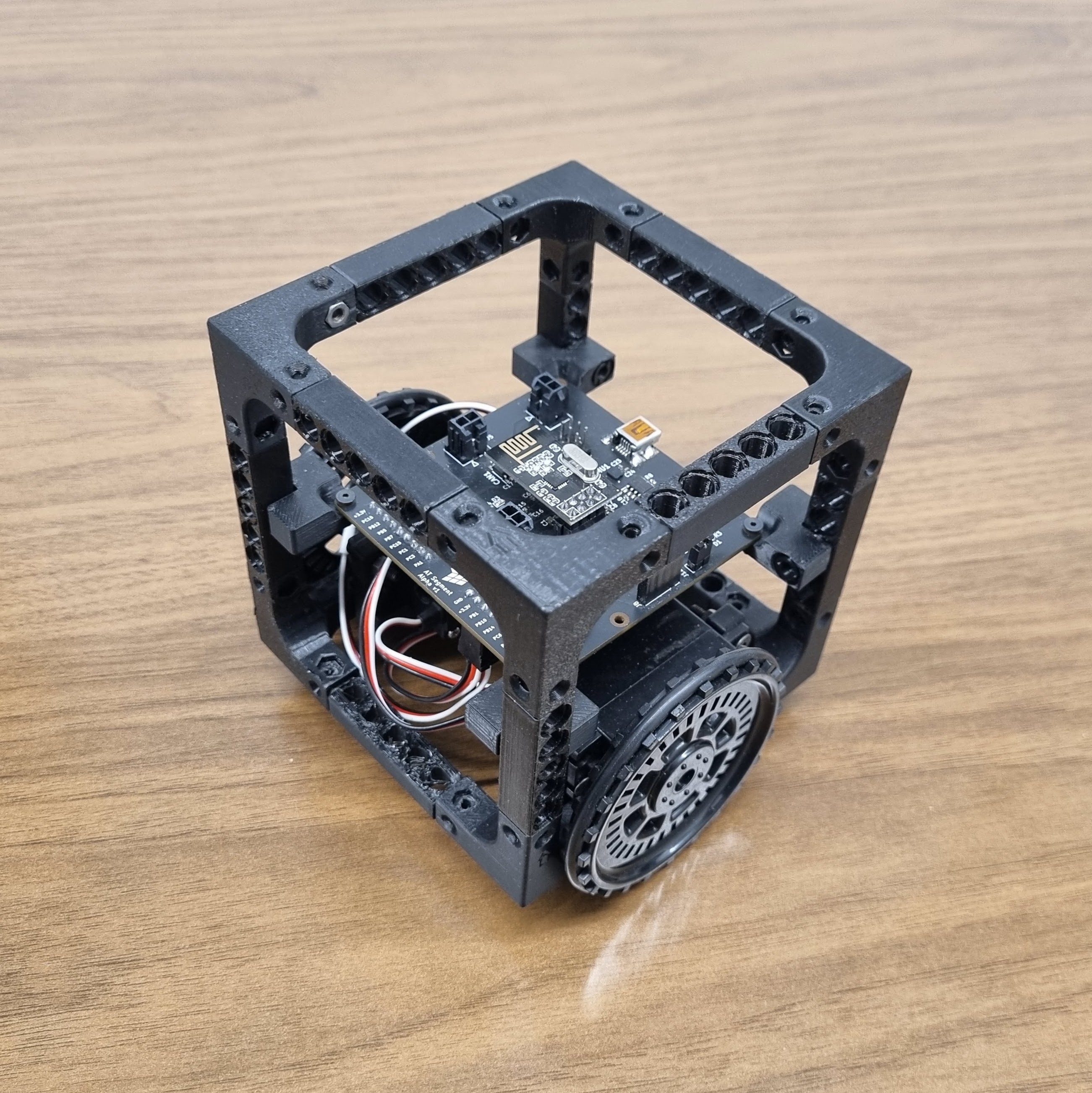
The vision for Modubot is to create a flexible, modular platform that promotes hands-on learning and skill development. By using cube-based modules, each with a unique electronic function, Modubot acts as a test platform for experimenting with:
This project is a chance to apply and refine engineering knowledge while exploring creative possibilities in robotics.
The current phase features a 2-wheeled robot designed as a proof of concept. It tests the General Purpose Module (GPM v1) along with:
However, the continuous servos faced tuning issues, preventing the robot from driving straight, highlighting the need to shift towards PID-controlled DC motors with encoders for precise control.
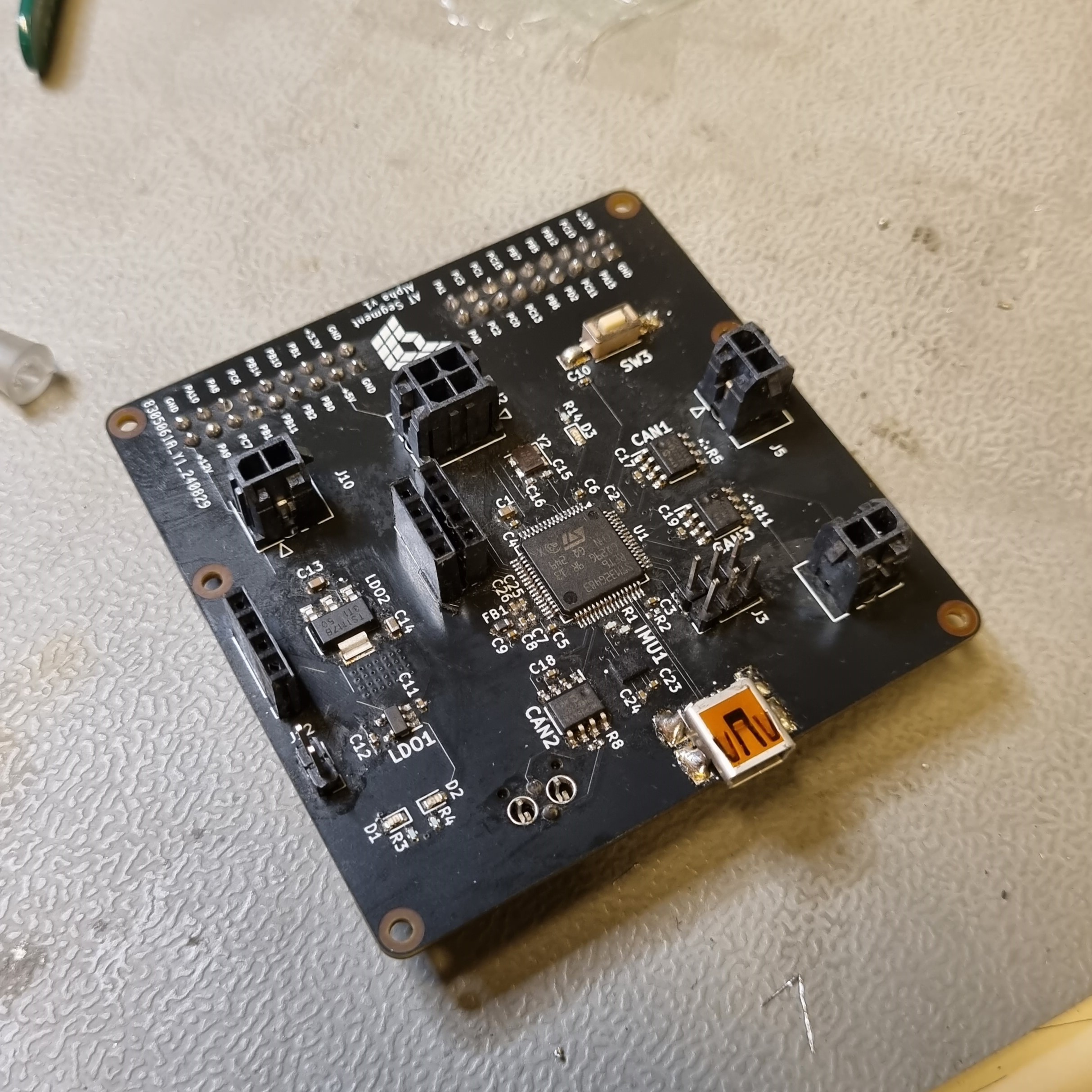
The first wave of designs has been completed. The initial PCB design was kept simple to avoid unnecessary points of failure. It functions as intended, though there are some design oversights:
These issues will be addressed in version 2, after learning more about system requirements.
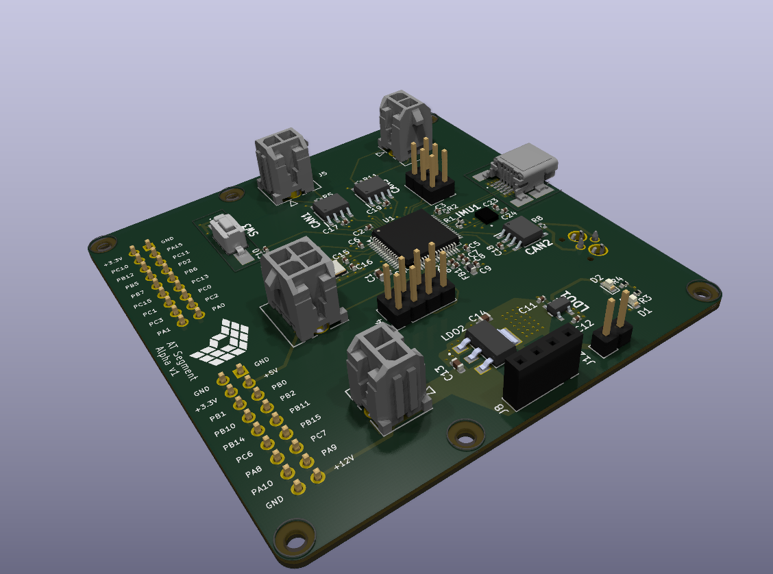
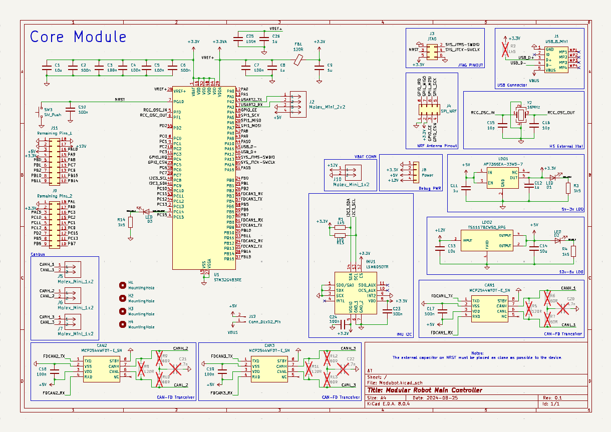
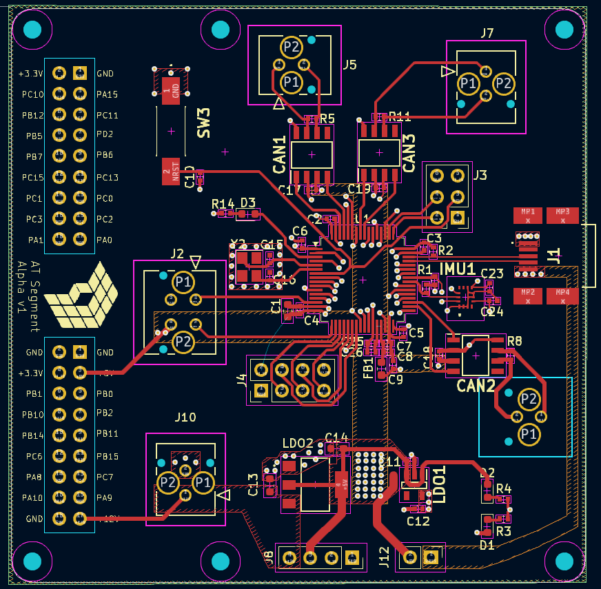
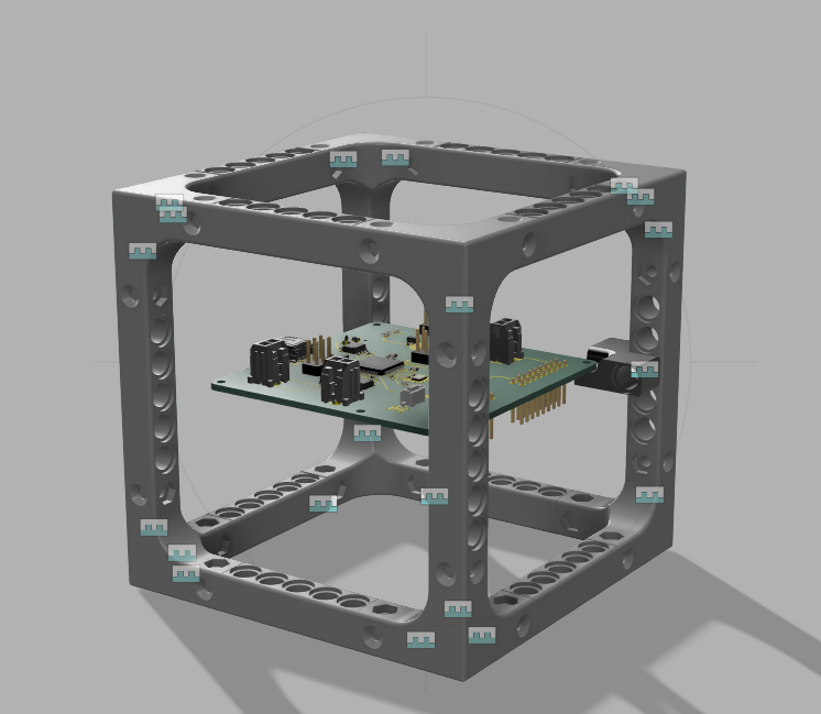
The 3D-printed structure has also been refined and is expected to remain unchanged unless major issues arise. For quick connections between modules and subcomponents (e.g., PCB bracket), 3D-printed Lego pins (scaled 1.25x) are being used, and for more permanent fixtures, M6 bolts can be inserted in the same holes. Initially, PETG was used for printing, but due to brittleness, the material has been changed to ABS, which is more ductile.
| Qty | Value | Footprint | References |
|---|---|---|---|
| 13 | 100n | Capacitor_SMD:C_0402_1005Metric | C2, C3, C4, C5, C6, C7, C10, C17, C18, C19, C23, C24, C25 |
| 6 | 1k5 | Resistor_SMD:R_0402_1005Metric | R1, R2, R3, R4, R14, R15 |
| 6 | MountingHole | MountingHole:MountingHole_2.2mm_M2 | H1, H2, H3, H3, H4, H4 |
| 5 | 1u | Capacitor_SMD:C_0402_1005Metric | C8, C9, C11, C12, C26 |
| 4 | Molex_Mini_1x2 | Personal:CON_430450224_MOL_VERT_1x2 | J5, J6, J7, J10 |
| 3 | 10u | Capacitor_SMD:C_0603_1608Metric | C1, C13, C14 |
| 3 | 120R | Resistor_SMD:R_0402_1005Metric | R5, R8, R11 |
| 3 | LED | LED_SMD:LED_0603_1608Metric | D1, D2, D3 |
| 3 | MCP2544WFDT-E_SN | Personal:SOIC127P600X175-8N | CAN1, CAN2, CAN3 |
| 2 | 10p | Capacitor_SMD:C_0402_1005Metric | C15, C16 |
| 1 | 120R | Inductor_SMD:L_0603_1608Metric | FB1 |
| 1 | 16MHz | Crystal:Crystal_SMD_3225-4Pin_3.2x2.5mm | Y2 |
| 1 | AP7366EA-33W5-7 | Personal:SOT95P285X140-5N | LDO1 |
| 1 | Conn_01x02_Pin | Connector_PinHeader_2.54mm:PinHeader_1x02_P2.54mm_Vertical | J12 |
| 1 | JTAG | Connector_PinHeader_2.54mm:PinHeader_2x03_P2.54mm_Vertical | J3 |
| 1 | LOGO | Personal:logofinal_1.5cm | G*** |
| 1 | LOGO | Personal:logofinal | G*** |
| 1 | LSM6DSOTR | Personal:LSM6DS3USTR | IMU1 |
| 1 | Molex_Mini_2x2 | Personal:CON_430450424_MOL_VERT_2x2 | J2 |
| 1 | Power | Connector_PinSocket_2.54mm:PinSocket_1x04_P2.54mm_Vertical | J8 |
| 1 | Remaining Pins_1 | Connector_PinHeader_2.54mm:PinHeader_2x09_P2.54mm_Vertical | J11 |
| 1 | Remaining Pins_2 | Connector_PinHeader_2.54mm:PinHeader_2x09_P2.54mm_Vertical | J9 |
| 1 | SPI_NRF | Connector_PinHeader_2.54mm:PinHeader_2x04_P2.54mm_Vertical | J4 |
| 1 | STM32G483RE | Package_QFP:LQFP-64_10x10mm_P0.5mm | U1 |
| 1 | SW_Push | Personal:Button_TL3302AF260QG | SW3 |
| 1 | TS1117BCW50_RPG | Personal:VREG_TS1117BCW50_RPG | LDO2 |
| 1 | USB_B_Mini | Personal:548190572 | J1 |
Hanqaqa/Easyduino
Easily dive into different PCB KiCad designs of the most popular microcontroller devboards


crmaykish/mackerel-68k
A series of single-board Motorola 68k computers with support for modern Linux

Twisted-Fields/acorn-robot-electronics
PCB hardware designs in KICAD for Acorn, the precision farming rover from Twisted Fields.


gfoot/compvideo6502
Composite/component video output for homebrew 6502 computers

It measures 70 × 70 mm and has 4 copper layers, 1.6 mm thick.
65 parts, built around the STM32G483RET6 and TS1117BCW50 RPG. The full list of its parts is on this page, with links to each part's symbol and footprint where PCBKit's library has them.
From the AmbroiseTau/Modubot repository on GitHub, at the commit this page was made from: the board is Core - Segment Alpha/v1/PCB/Modubot.kicad_pcb and its schematic Core - Segment Alpha/v1/PCB/Modubot.kicad_sch. PCBKit opens the board in the browser, with nothing to install.
Its repository states no licence, so its author keeps all rights: ask AmbroiseTau before reusing the design.