

2 layers36.2 × 52.7 mm

 AlishaG15/Lightbox-MedTechPrototyping
Interactive LED system with custom PCB and real-time feedback.
Lightbox MedTechPrototyping is an open-source printed circuit board by AlishaG15, from the AlishaG15/Lightbox-MedTechPrototyping repository on GitHub. It is a 2-layer board of 85.2 × 57.2 mm with 18 parts on 35 nets, routed with 63 tracks and 0 vias.
It is built around the B02B-XASK-1 and IRFZ44N. Its parts include 7 connectors, 3 resistors and 3 transistors. It belongs with the AVR (ATmega, ATtiny) boards of this library.
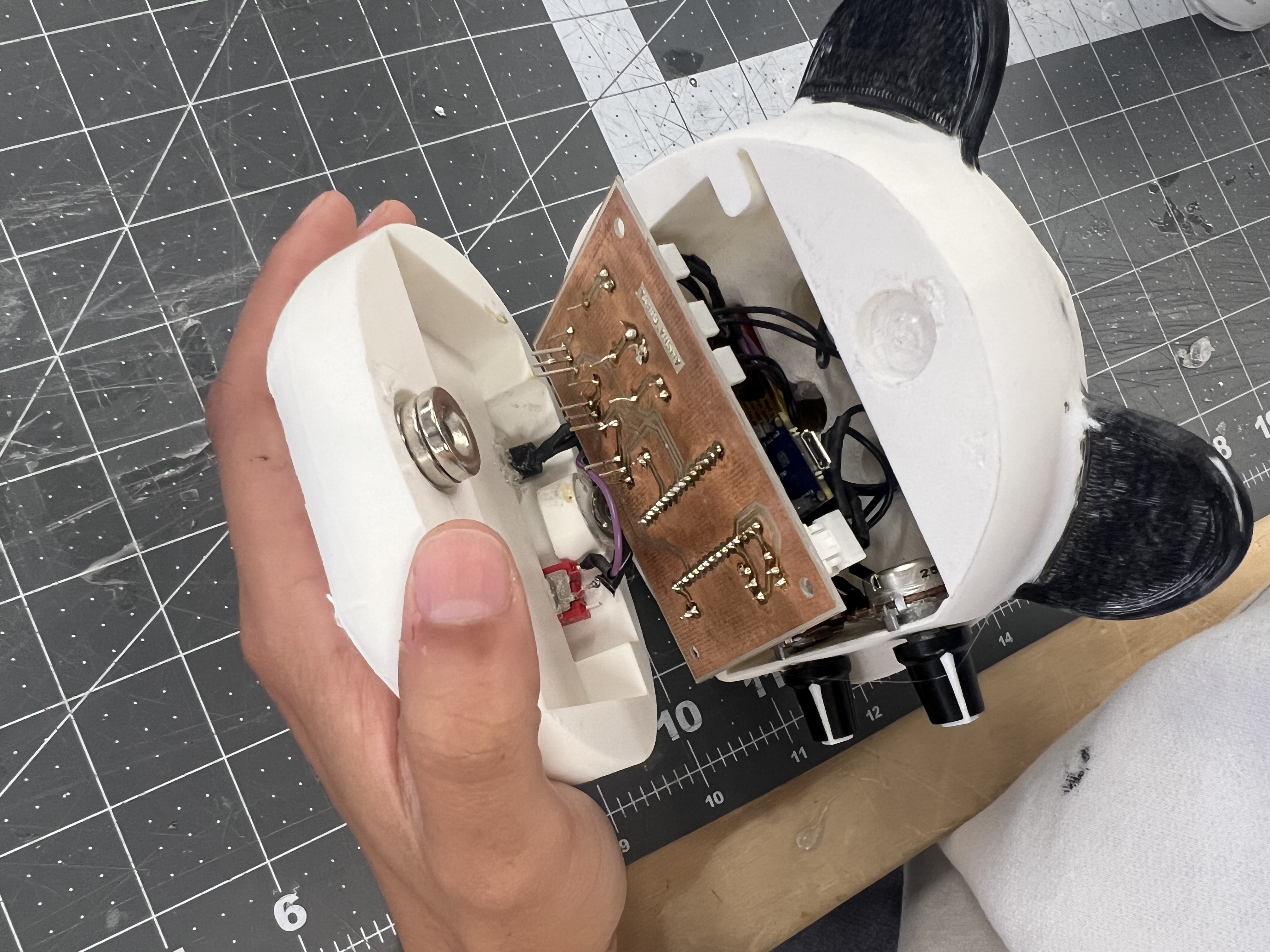
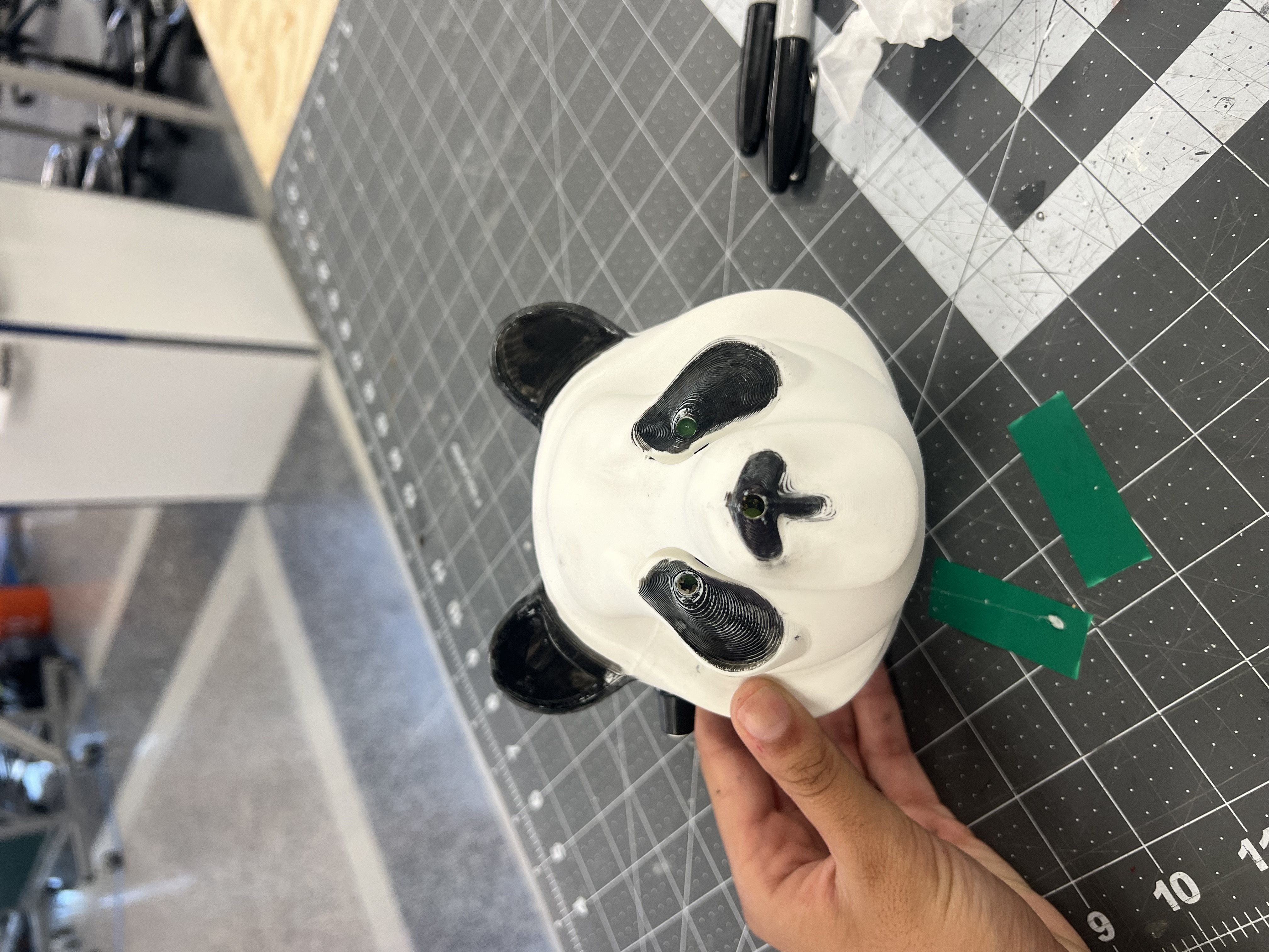
A custom embedded systems project built for BME 254 at Duke University — a 3D-printed panda enclosure housing a hand-soldered PCB, Arduino Nano Every, and three independently controlled LEDs (two eyes and a nose).
When a button is pressed, the panda's eyes light up for 5 seconds and its nose blinks for 10 seconds. The brightness of the eyes and blink rate of the nose are each controlled by a dedicated potentiometer mounted in the ears. An onboard heartbeat LED blinks at 1 Hz in all states to confirm the device is running.
| Component | Detail |
|---|---|
| Microcontroller | Arduino Nano Every (ATmega4809) |
| PCB | Custom single-sided board, hand-milled and soldered |
| LED drivers | IRFZ44 N-channel MOSFETs |
| Enclosure | 3D-printed PLA, two-part snap fit |
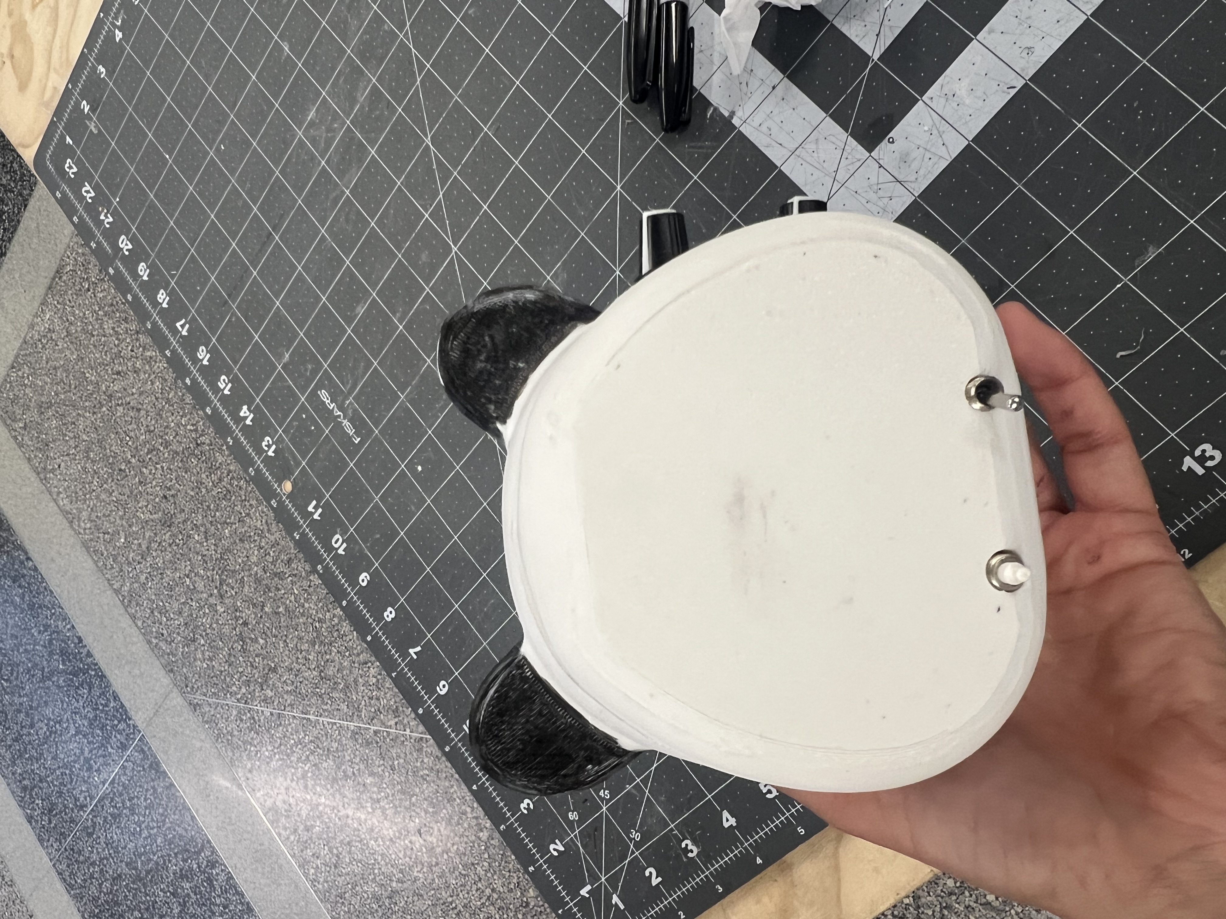
| Power | 9 V battery with SPST toggle switch |
| Controls | SPST push button + 2× 10 kΩ potentiometers |
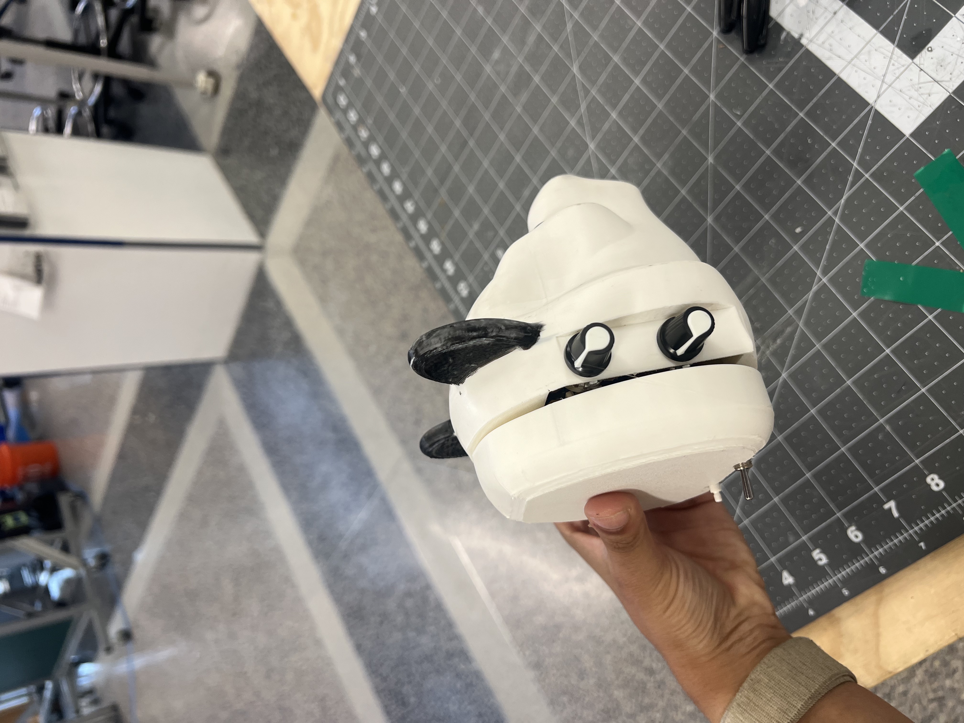
Written in C++ using the Arduino framework via PlatformIO. Key design decisions:
IDLE, ANALOG_READ, and LED_OUTPUTattachInterrupt() — no polling in the main loopmillis() — no delay() calls anywhereanalogWrite(), mapped linearly from the potentiometer ADC readingdigitalWrite() to avoid the Nano Every's 255/256 PWM artifact#define macros at the top of the fileIDLE ──(button press)──▶ ANALOG_READ ──▶ LED_OUTPUT ──(10 s elapsed)──▶ IDLEAll measurements taken with a Tektronix TBS 1102B oscilloscope.
Heartbeat LED
Eye LED brightness (vs. potentiometer resistance)
Nose LED blink rate (vs. potentiometer resistance)
| Assembled | Back panel |
|---|---|
 |  |
| Internals (PCB) | Internals (Arduino + connectors) |
|---|---|
| 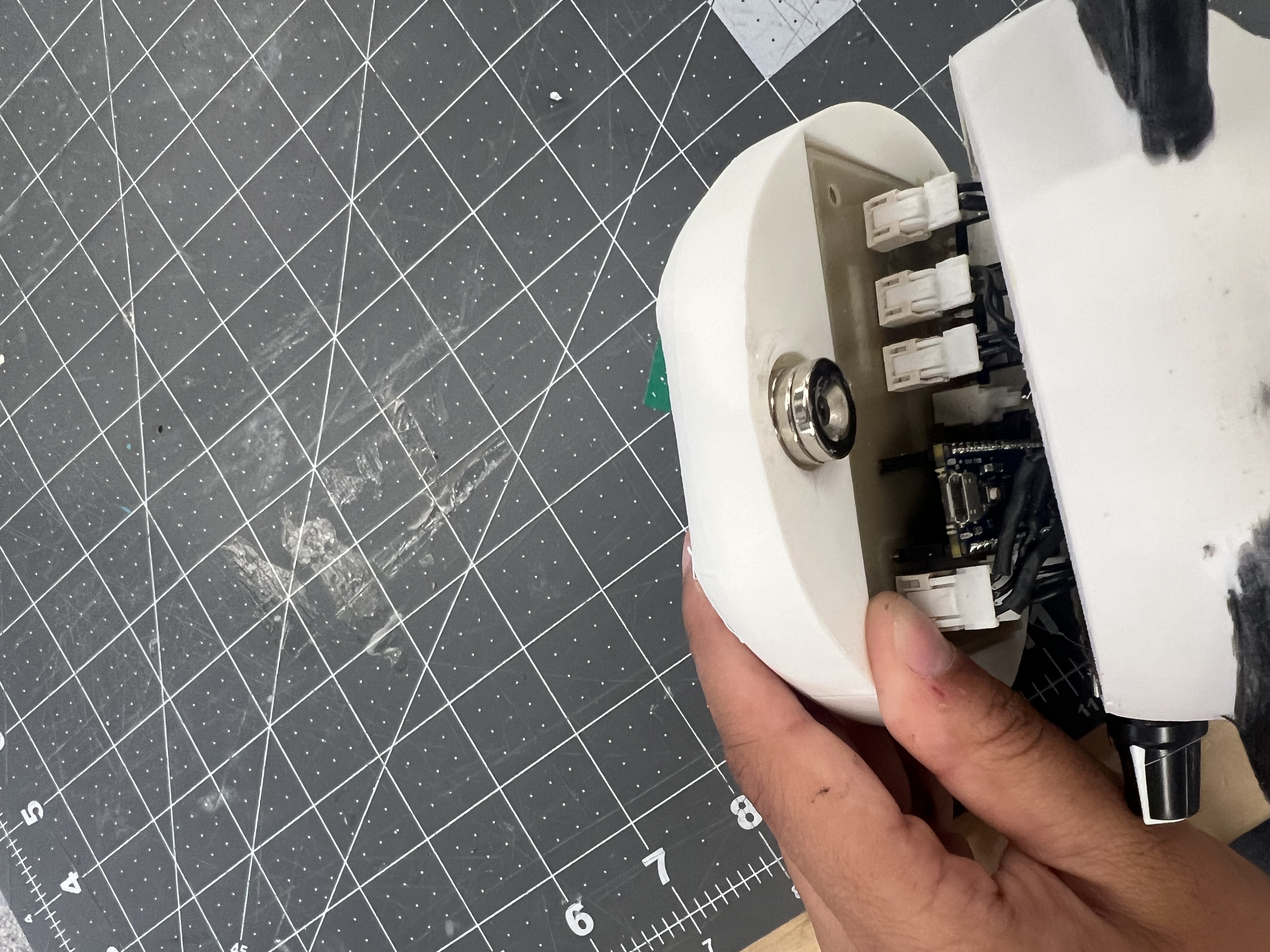 |
| Qty | Value | Footprint | References |
|---|---|---|---|
| 4 | MountingHole | MountingHole:MountingHole_3.2mm_M3 | H1, H2, H3, H4 |
| 3 | 1k | Resistor_THT:R_Axial_DIN0207_L6.3mm_D2.5mm_P10.16mm_Horizontal | R1, R2, R3 |
| 3 | B02B-XASK-1 | Connector_JST:JST_XA_B02B-XASK-1_1x02_P2.50mm_Vertical | J57, J69, J71 |
| 3 | IRFZ44N | Package_TO_SOT_THT:TO-220-3_Vertical | Q1, Q2, Q3 |
| 2 | Conn_01x02_Pin | Connector_JST:JST_XA_B02B-XASK-1_1x02_P2.50mm_Vertical | J12, J23 |
| 1 | Arduino_Nano_Every | Module:Arduino_Nano | A1 |
| 1 | POT_BLINK_CONN | Connector_PinSocket_2.54mm:PinSocket_1x03_P2.54mm_Vertical | J41 |
| 1 | POT_BRIGHT_CONN | Connector_PinSocket_2.54mm:PinSocket_1x03_P2.54mm_Vertical | J35 |

NikodemBartnik/Mini-Mars-Rover
Educational robotic platform made to look like a mini mars rover


NikodemBartnik/Pico-Watering-System
Raspberry Pi Pico based automated watering system for your garden

BenjamimKrug/robo_humanoide
Repositorio para arquivos gerais necessários para o desenvolvimento do Robô humanoide

2technology/g-board
ESP32 IoT Home automation PCB - 1 * 12V relay, 4 * input button connector with HW debounce, 4 * ws2812b output

AvishkaVishwa/12V-DC-Motor-Speed-Controller-PCB-Design-using-KiCAD
using 555 timer is at Astable mode

RichardBenear/DDScopeX-Hardware
Hardware documentation for Direct Drive Scope
It measures 85.2 × 57.2 mm and has 2 copper layers, 1.6 mm thick.
18 parts, built around the B02B-XASK-1 and IRFZ44N. The full list of its parts is on this page, with links to each part's symbol and footprint where PCBKit's library has them.
From the AlishaG15/Lightbox-MedTechPrototyping repository on GitHub, at the commit this page was made from: the board is circuit/circuit.kicad_pcb and its schematic circuit/circuit.kicad_sch. PCBKit opens the board in the browser, with nothing to install.
Its repository states no licence, so its author keeps all rights: ask AlishaG15 before reusing the design.