2 layers18.3 × 14.1 mm

 Akkiesoft/ws_lcd128_bo
WaveShare RP2040-LCD-1.28のGPIOピンでアレコレするボード各種のKiCadデータ
Ws lcd128 bo is an open-source printed circuit board by Akkiesoft, from the Akkiesoft/ws_lcd128_bo repository on GitHub. It is a 2-layer board of 18.3 × 31.1 mm with 4 parts on 40 nets, routed with 378 tracks and 14 vias.
WaveShare RP2040-LCD-1.28のGPIOポートを利用した各種基板データ置き場です。
GPIOの配置などはWaveShareのWikiを参照してください。
1.27mmピッチのGPIOピンを2.54mmピットに変換するブレイクアウトです。適当に空けた2.6mmの穴3つ付き。
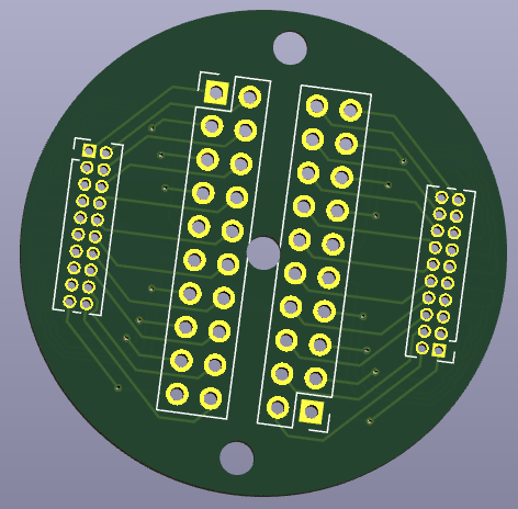
基板1枚あたりに必要な部材は以下のとおりです。
RP2040-LCD-1.28にWIZnetチップ搭載Ethernetモジュールを搭載するための変換ボードです。
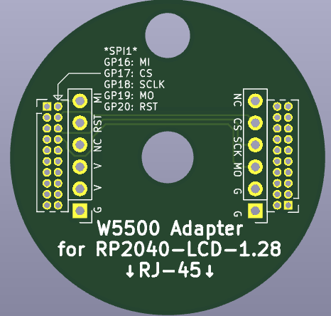
基板1枚あたりに必要な部材は以下のとおりです。
GPIO配置は以下のとおりです。
MIT License
2025 Akkiesoft
| Qty | Value | Footprint | References |
|---|---|---|---|
| 2 | Conn_02x10_Odd_Even | Connector_PinHeader_1.27mm:PinHeader_2x10_P1.27mm_Vertical | J1, J2 |
| 2 | Conn_02x10_Odd_Even | Connector_PinHeader_2.54mm:PinHeader_2x10_P2.54mm_Vertical | J3, J4 |

joypad-ai/joypad-os
Universal controller firmware for building adapters, dongles, and custom controllers.


hackclub/OnBoard
💡 Join 1,000 teenagers and make your first PCB with a $100 grant!

tardate/LittleArduinoProjects
a collection of "Little Electronic & Arduino Projects", most involving electronics or an Arduino in one way or another!

drandyhaas/KiCadRoutingTools
A set of Python/Rust tools to aid routing in KiCad

osy/XG_Mobile_Station
Open source eGPU dock for ROG Ally and ROG Flow

Luos-io/luos_engine
Open-source and real-time orchestrator for cyber-physical-systems, to easily design, test and deploy embedded applications and digital twins.

NVNTLabs/switch2-SDEX2M2
Micro SD Express to M.2 NVME Adapter for Nintendo Switch 2
It measures 18.3 × 31.1 mm and has 2 copper layers, 1.6 mm thick.
4 parts. The full list of its parts is on this page, with links to each part's symbol and footprint where PCBKit's library has them.
From the Akkiesoft/ws_lcd128_bo repository on GitHub, at the commit this page was made from: the board is board-breakout/ws_lcd128_bo.kicad_pcb and its schematic board-breakout/ws_lcd128_bo.kicad_sch. PCBKit opens the board in the browser, with nothing to install.
Its repository states no licence, so its author keeps all rights: ask Akkiesoft before reusing the design.