2 layers97.2 × 59.1 mm
ArmLEDsPrototype
hackclub/OnBoard
💡 Join 1,000 teenagers and make your first PCB with a $100 grant!
35 parts915

 AhmedAmineSebti/NXP-CUP
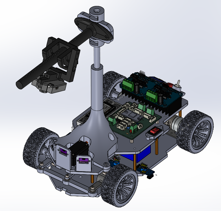
The car uses an onboard smart camera to detect track lines, a custom PCB centered on a Teensy 4.1 microcontroller to run the real-time control loops, and a set of IR/ToF sensors for start-line detection and obstacle…
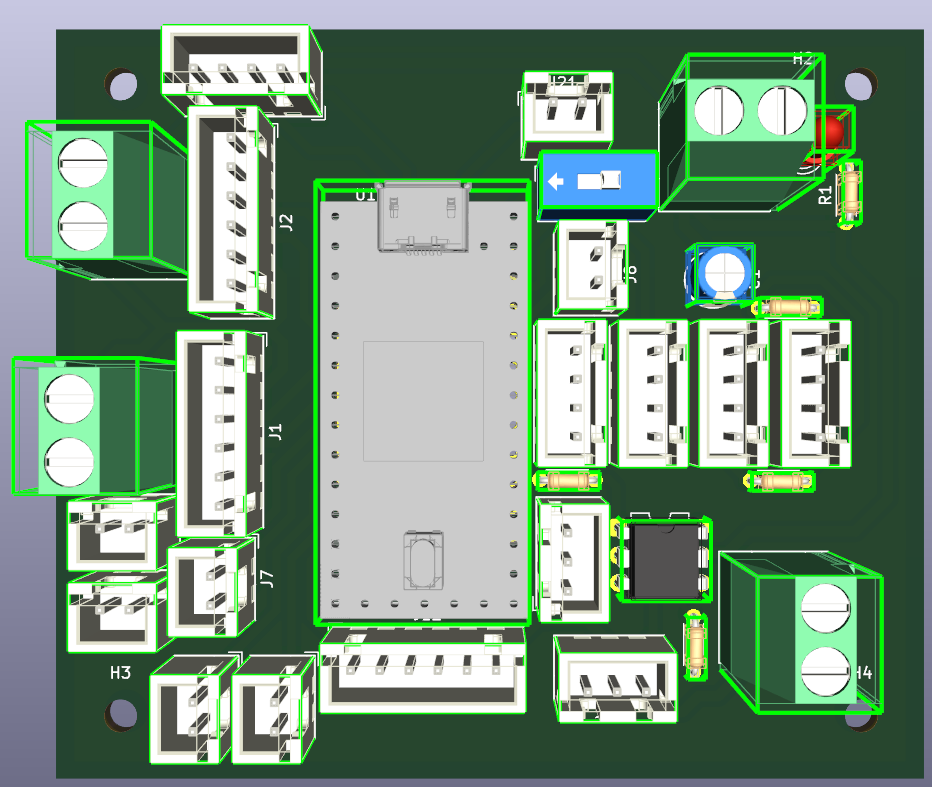
Shield teensy4.0 is an open-source printed circuit board by AhmedAmineSebti, from the AhmedAmineSebti/NXP-CUP repository on GitHub. It is a 2-layer board of 79.6 × 68.8 mm with 35 parts on 43 nets, routed with 245 tracks and 0 vias.
Its parts include 21 connectors, 5 resistors, 2 ICs, 1 capacitor and 1 diode. It belongs with the NXP (LPC, Kinetis, i.MX RT) boards of this library.
The car uses an onboard smart camera to detect track lines, a custom PCB centered on a Teensy 4.1 microcontroller to run the real-time control loops, and a set of IR/ToF sensors for start-line detection and obstacle stopping. This README covers the mechanical design and electronic architecture of the vehicle.
The system is organized in three functional layers around the Teensy 4.1:
| Component | Reference | Role | Interface |
|---|---|---|---|
| Microcontroller | Teensy 4.1 | Central processing | — |
| Camera | Pixy2 v2 | Line detection | SPI |
| IR sensors | TCRT5000 × 4 | Start/finish line | GPIO |
| ToF sensor | VL53L0X | Obstacle stop | I²C |
| Steering servo | MG996R | Wheel steering | PWM |
| Drive motor | Brushed DC motor | Propulsion | PWM + H-bridge |
| Display | 0.96" OLED | Status display | I²C |
| Buttons | Push button × 2 | Mode selection/Race start | GPIO |
| Wheel encoders | Quadrature, 408 CPR | Speed/position feedback | GPIO (interrupt) |
| Power source | 3S LiPo (12.6 V) | Energy source | — |
| Pin | Peripheral | Signal | Interface |
|---|---|---|---|
| 12 | Pixy2 Camera | SPI RX (MISO) | SPI0 |
| 11 | Pixy2 Camera | SPI TX (MOSI) | SPI0 |
| 13 | Pixy2 Camera | SPI SCK | SPI0 |
| 10 | Pixy2 Camera | SPI CS | SPI0 |
| 18 | VL53L0X / OLED | I²C SDA | I²C0 |
| 19 | VL53L0X / OLED | I²C SCL | I²C0 |
| 17 | MG996R Servo | PWM | PWM |
| 6-7-22-23 | IBTs | PWM (speed) | PWM |
| 14–17 | IR sensors 1–4 | Start line | GPIO (pull-up) |
| 2-3-4-5 | Rotary encoder | CH A/B | GPIO (interrupt) |
| 8 | Mode button | SW | GPIO |
| 9 | Start button | SW | GPIO |
| Qty | Value | Footprint | References |
|---|---|---|---|
| 7 | Conn_01x02 | Connector_JST:JST_XH_B2B-XH-A_1x02_P2.50mm_Vertical | J5, J6, J7, J8, J18, J19, J21 |
| 5 | Conn_01x04 | Connector_JST:JST_XH_B4B-XH-A_1x04_P2.50mm_Vertical | J11, J13, J14, J15, J20 |
| 5 | R | Resistor_THT:R_Axial_DIN0204_L3.6mm_D1.6mm_P5.08mm_Horizontal | R1, R2, R3, R4, R5 |
| 4 | MountingHole | MountingHole:MountingHole_3mm | H1, H2, H3, H4 |
| 4 | Screw_Terminal_01x02 | TerminalBlock_Phoenix:TerminalBlock_Phoenix_MKDS-1,5-2_1x02_P5.00mm_Horizontal | J3, J4, J9, J16 |
| 3 | Conn_01x06 | Connector_JST:JST_XH_B6B-XH-A_1x06_P2.50mm_Vertical | J1, J2, J12 |
| 2 | Conn_01x03 | Connector_JST:JST_XH_B3B-XH-A_1x03_P2.50mm_Vertical | J10, J17 |
| 1 | 4N25 | Package_DIP:DIP-6_W7.62mm | U2 |
| 1 | C_Polarized | Capacitor_THT:CP_Radial_D5.0mm_P2.50mm | C1 |
| 1 | DEV-15583 | DEV-15583:MODULE_DEV-15583 | U1 |
| 1 | LED | LED_THT:LED_D3.0mm | D1 |
| 1 | SW_SPST | Button_Switch_THT:SW_DIP_SPSTx01_Slide_9.78x4.72mm_W7.62mm_P2.54mm | SW1 |
hackclub/OnBoard
💡 Join 1,000 teenagers and make your first PCB with a $100 grant!


ozel/DIY_particle_detector
A mobile low-cost spectrometer for measuring radioactivity and the energy of ionising radiation like alpha particles and electrons

Seeed-Studio/OSHW-reCamera-Series
reCamera is a series of open-source AI cameras.


It measures 79.6 × 68.8 mm and has 2 copper layers, 1.6 mm thick.
35 parts. The full list of its parts is on this page, with links to each part's symbol and footprint where PCBKit's library has them.
From the AhmedAmineSebti/NXP-CUP repository on GitHub, at the commit this page was made from: the board is éléctronique/shield_teensy4.0/shield_teensy4.0.kicad_pcb and its schematic éléctronique/shield_teensy4.0/shield_teensy4.0.kicad_sch. PCBKit opens the board in the browser, with nothing to install.
Its repository states no licence, so its author keeps all rights: ask AhmedAmineSebti before reusing the design.