Skip to the content
2 layers28 × 18 mmRelayDriver, the printed circuit board in 3D
Size
28 × 18 mm
Copper layers
2
Thickness
1.6 mm
Parts
4
Nets
22
Pads
52
Tracks, vias
129, 4
Pours
1
Routed
Yes
KiCad
KiCad 5 (file 20171130)
Created
25 Jan 2024
Updated
18 Jan 2026

Overview

RelayDriver is an open-source printed circuit board by AgOpenGPS-Official, from the AgOpenGPS-Official/Rate_Control repository on GitHub, published under the GPL-3.0 licence. It is a 2-layer board of 28 × 18 mm with 4 parts on 22 nets, routed with 129 tracks and 4 vias.

Its parts include 3 connectors and 1 IC.

README

README.md

Nano RC12-3

  • uses a Nano (with ENC28J60 Ethernet shield) & an on-board mounted Cytron for rate control
    • 1 or 2 MD13S for rate control
  • self assembled through-hole board, least expensive
  • controls two rates
  • can be connected to a relay module with a 20 pin cable or dupont connectors
  • work switch
  • pressure switch
  • [OSHPARK](https://oshpark.com/shared_projects/UU8e90h9 RC12-3

Teensy 4.1 RC11-2

  • uses a Teensy & an on-board mounted Cytron for rate control
    • either (1) MD13S for single rate control
    • or (1) MDD10A for dual rate control
  • small components are surface mount parts
  • Teensy Ethernet
  • can control two rates and eight sections
    • 8 relays (SPDT 12V output)
    • (1) 5V or 12V analog (pressure) input, potentiometer adjustable filtering
    • (2) optically isolated digital (rate/pulse) inputs (5V or 12V)
  • 3.3V I2C headers (Qwiic)
    • supports optional external RelayDriver5 I2C board
  • work switch
  • canbus RC11-2

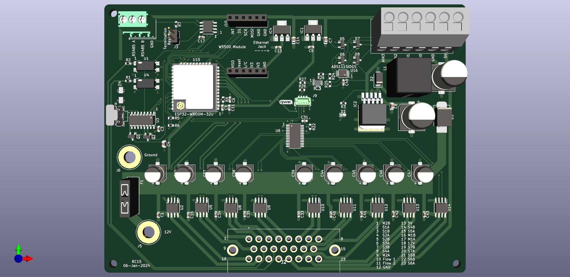
ESP32 RC15

  • uses an ESP32 (optional W5500 Ethernet Module)
  • mostly surface mount parts
  • can control two rates and 7-14 sections
    • (2) DRV8870 motor drivers with reversible outputs for rates
    • (7) DRV8870 motor drivers for 7 reversible (motorized ball valve) outputs
  • (4) 5V analog inputs (or 2 differential inputs)
  • (2) optically isolated digital (rate/pulse) inputs, up to 12V
  • RS485 chip & header
  • 3.3V I2C header
    • supports optional external RelayDriver5 I2C board ESP32-RC15

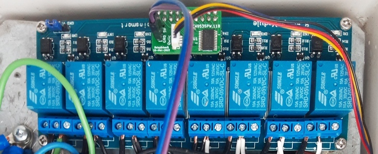
RelayDriver5

  • PCA9535 based I2C IO expander
  • designed to plug into 8 or 16 channel relay board with Qwiic cable RelayDriver5 photo

Firmware

https://github.com/SK21/AOG_RC

Parts

4
QtyValueFootprintReferences
1 Connector_PinHeader_2.54mm:PinHeader_1x02_P2.54mm_VerticalJ3
1 Connector_PinSocket_2.54mm:PinSocket_2x10_P2.54mm_VerticalJ2
1PCA9535PW,118MyFootprints:SOP65P640X110-24NU1
1QwiicMyFootprints:Qwic_verticalJ1

More from AgOpenGPS-Official/Rate_Control

5
  • 4 layers159 × 130 mmRC11, the printed circuit board in 3D

    RC11

    AgOpenGPS-Official/Rate_Control

    106 parts20GPL-3.0
  • 2 layers145 × 108 mmRC15, the printed circuit board in 3D

    RC15

    AgOpenGPS-Official/Rate_Control

    93 parts20GPL-3.0
  • 2 layers89 × 100 mmRC12-3, the printed circuit board in 3D

    RC12-3

    AgOpenGPS-Official/Rate_Control

    41 parts20GPL-3.0
  • 2 layers110 × 54 mmSwitchbox3, the printed circuit board in 3D

    Switchbox3

    AgOpenGPS-Official/Rate_Control

    24 parts20GPL-3.0
  • 2 layers89 × 52 mmSW2, the printed circuit board in 3D

    SW2

    AgOpenGPS-Official/Rate_Control

    10 parts20GPL-3.0

Similar boards

  • 2 layers18.5 × 26 mm24g2usb rp2350zero, the printed circuit board in 3D

    24g2usb rp2350zero

    joypad-ai/joypad-os

    Universal controller firmware for building adapters, dongles, and custom controllers.

    4 parts1.7kApache-2.0
  • 2 layers116 × 33 mm966595-1 and 963356-1, the printed circuit board in 3D

    966595-1 and 963356-1

    rusefi/rusefi

    rusefi - GPL internal combustion engine control unit

    4 parts1.2k
  • 2 layers19 × 18 mmDaughter board, the printed circuit board in 3D

    Daughter board

    hackclub/OnBoard

    💡 Join 1,000 teenagers and make your first PCB with a $100 grant!

    4 parts915
  • 2 layers24.8 × 24.8 mmNrf24 breakout, the printed circuit board in 3D

    Nrf24 breakout

    tardate/LittleArduinoProjects

    a collection of "Little Electronic & Arduino Projects", most involving electronics or an Arduino in one way or another!

    4 parts803MIT
  • 2 layers26 × 20 mmCap chain, the printed circuit board in 3D

    Cap chain

    drandyhaas/KiCadRoutingTools

    A set of Python/Rust tools to aid routing in KiCad

    4 parts744MIT
  • 2 layers34.7 × 20 mmXG Station Power MSI, the printed circuit board in 3D

    XG Station Power MSI

    osy/XG_Mobile_Station

    Open source eGPU dock for ROG Ally and ROG Flow

    4 parts712CC-BY-4.0
  • 2 layers20.3 × 24.5 mmJack power input, the printed circuit board in 3D

    Jack power input

    Luos-io/luos_engine

    Open-source and real-time orchestrator for cyber-physical-systems, to easily design, test and deploy embedded applications and digital twins.

    4 parts546MIT

Questions

How big is the RelayDriver PCB?

It measures 28 × 18 mm and has 2 copper layers, 1.6 mm thick.

What parts does the RelayDriver use?

4 parts. The full list of its parts is on this page, with links to each part's symbol and footprint where PCBKit's library has them.

Where can I download the RelayDriver KiCad files?

From the AgOpenGPS-Official/Rate_Control repository on GitHub, at the commit this page was made from: the board is RelayDriver5/RelayDriver.kicad_pcb and its schematic ESP32/RC15/Analog.kicad_sch. PCBKit opens the board in the browser, with nothing to install.

Can I use the RelayDriver design in my own project?

Its repository publishes it under the GPL-3.0 licence: you may reuse it on that licence's terms (keep the author's notice, and for a copyleft licence share your changes alike).