2 layers43.9 × 27.7 mm

 AamirKPathan/Titan-Driver-Pad
A custom PCB-based button controller project for FRC 5719. The controller uses a Seeed Studio XIAO ESP32-C3, eight Cherry MX-style mechanical switches, and a small OLED display.
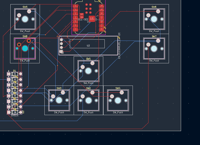
DriverPad is an open-source printed circuit board by AamirKPathan, from the AamirKPathan/Titan-Driver-Pad repository on GitHub. It is a 2-layer board of 120 × 85 mm with 19 parts on 22 nets, routed with 151 tracks and 8 vias.
Its parts include 8 diodes, 8 switches and 2 ICs.
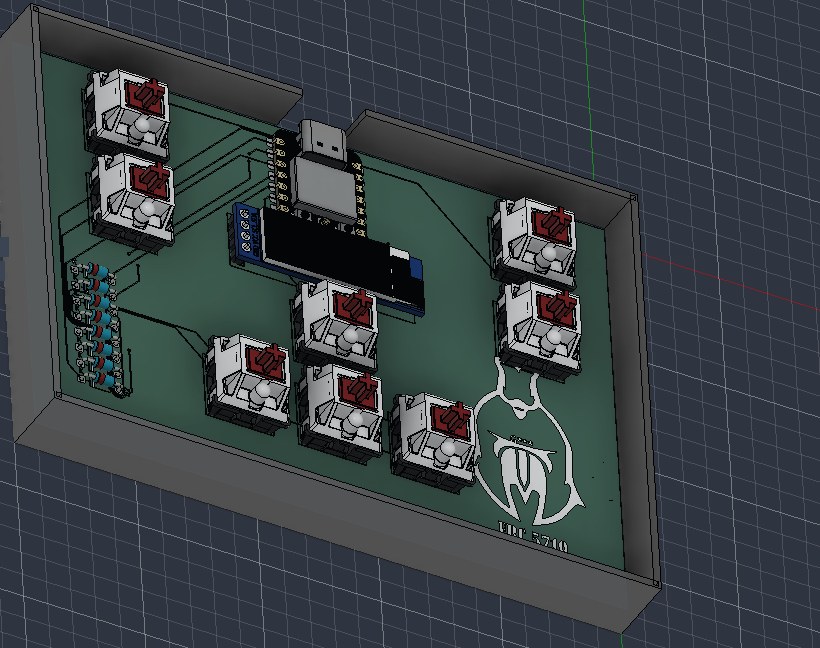
A custom PCB-based button controller project for FRC 5719. The controller uses a Seeed Studio XIAO ESP32-C3, eight Cherry MX-style mechanical switches, and a small OLED display.
Enclosure: Bottom case only. There is no top case or cover.
| Final product | PCB render |
|---|---|
| 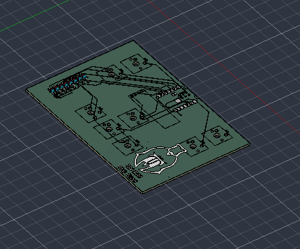 |
| Component | Details |
|---|---|
| Microcontroller | Seeed Studio XIAO ESP32-C3 |
| Switches | 8 Cherry MX-style mechanical switches |
| Display | 0.91-inch SSD1306 OLED, 128 × 32, I2C |
| PCB design software | KiCad |
| Firmware environment | VS Code + PlatformIO |
| Enclosure | Bottom case only; no top case |
| Switch | Intended Input |
|---|---|
| SW1 | Left stick up (W / 1) |
| SW2 | Left stick left (A / 2) |
| SW3 | Left stick down (S / 3) |
| SW4 | Left stick right (D / 4) |
| SW5 | L2 |
| SW6 | R2 |
| SW7 | R1 |
| SW8 | L1 |
Controls are intended to remain active while a switch is held and deactivate when released. Opposite directions cancel each other out.
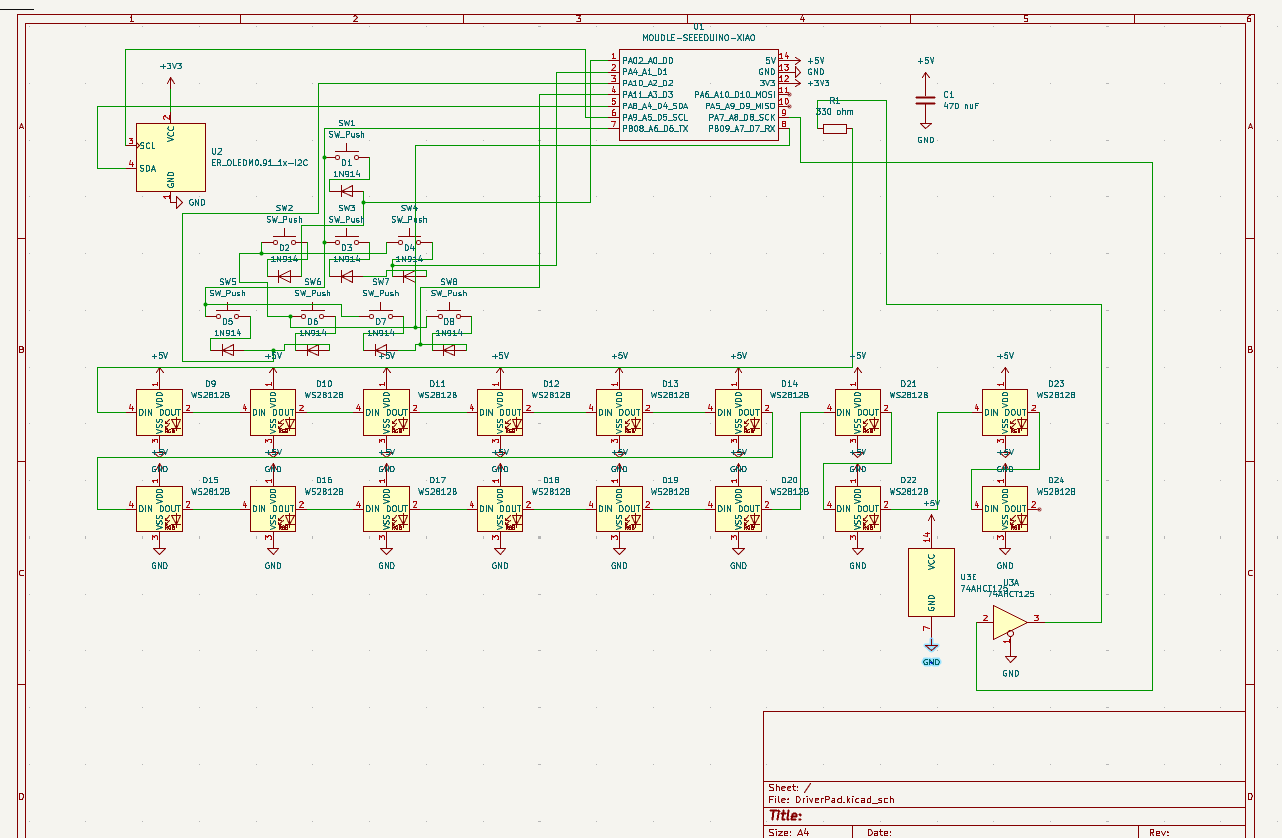
| Signal | XIAO Pin Label | GPIO |
|---|---|---|
| Row 1 | D0 / A0 | 2 |
| Row 2 | D1 / A1 | 3 |
| Row 3 | D2 / A2 | 4 |
| Row 4 | D3 / A3 | 5 |
| Column 1 | D6 / TX | 8 |
| Column 2 | D7 / RX | 9 |
| Column 1 (GPIO 8) | Column 2 (GPIO 9) | |
|---|---|---|
| Row 1 (GPIO 2) | SW1 | SW5 |
| Row 2 (GPIO 3) | SW2 | SW6 |
| Row 3 (GPIO 4) | SW3 | SW7 |
| Row 4 (GPIO 5) | SW4 | SW8 |
Note: The physical matrix wiring and diode orientation have not yet been verified. Confirm them against the final KiCad schematic and PCB when the hardware arrives.
| OLED Signal | XIAO Pin Label | GPIO |
|---|---|---|
| SDA | D4 / A4 / SDA | 6 |
| SCL | D5 / A5 / SCL | 7 |
The firmware currently uses I2C address 0x3C. Some OLED modules use 0x3D.
The firmware is developed using VS Code and PlatformIO with the Arduino framework for ESP32-C3.
Open a terminal in the Firmware directory and run:
pio runOnce the hardware arrives, connect the XIAO ESP32-C3 through USB and run:
pio run --target uploadpio device monitorThe firmware is intended to output controller states in the following format:
STATE,UP,LEFT,DOWN,RIGHT,L1,L2,R1,R2Each state is represented by 0 (inactive) or 1 (active).
Once the hardware arrives:
The project may be organized as follows:
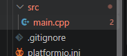
Titan Driver Pad/
├── Firmware/
│   ├── platformio.ini
│   └── src/
│       └── main.cpp
├── Hardware/
│   └── KiCad project files
└── README.md
Adjust the folder names in this section to match the actual project structure.
Developed for FRC Team 5719 — Pink Titans.
| Qty | Value | Footprint | References |
|---|---|---|---|
| 8 | 1N914 | Diode_THT:D_DO-35_SOD27_P7.62mm_Horizontal | D1, D2, D3, D4, D5, D6, D7, D8 |
| 8 | SW_Push | Button_Switch_Keyboard:SW_Cherry_MX_1.00u_PCB | SW1, SW2, SW3, SW4, SW5, SW6, SW7, SW8 |
| 1 | ER_OLEDM0.91_1x-I2C | Display:ER_OLEDM0.91_1x-I2C | U2 |
| 1 | LOGO | PCB:logo | G*** |
| 1 | MOUDLE-SEEEDUINO-XIAO | RF_Module:MCU_Seeed_ESP32C3 | U1 |

hackclub/OnBoard
💡 Join 1,000 teenagers and make your first PCB with a $100 grant!

polpo/picogus
Emulation of ISA sound cards and CD-ROM on Raspberry Pi Pico (GUS, SB/Adlib, MPU-401, Tandy, CMS, Panasonic CD-ROM) with USB mouse/joystick support


nkitanov/iaq_board
IAQ Board is a DIY (Do-It-Yourself) device for measuring internal air quality


Ardumower/ardumower
Develop an open source robotic lawn mower (HW+SW reference platform)

zmaker/arduino_cookbook
gli sketch del nuovo progetto Arduino Cookbook e dei video di YouTube
It measures 120 × 85 mm and has 2 copper layers, 1.6 mm thick.
19 parts. The full list of its parts is on this page, with links to each part's symbol and footprint where PCBKit's library has them.
From the AamirKPathan/Titan-Driver-Pad repository on GitHub, at the commit this page was made from: the board is Driver/Production/PCB/DriverPad.kicad_pcb and its schematic Driver/Production/PCB/DriverPad.kicad_sch. PCBKit opens the board in the browser, with nothing to install.
Its repository states no licence, so its author keeps all rights: ask AamirKPathan before reusing the design.