2 layers38.5 × 38.5 mm
 AT882/Falcon-F4-Flight-controller
Custom STM32F405-based flight controller designed for UAV, FPV and aerial robotics applications.
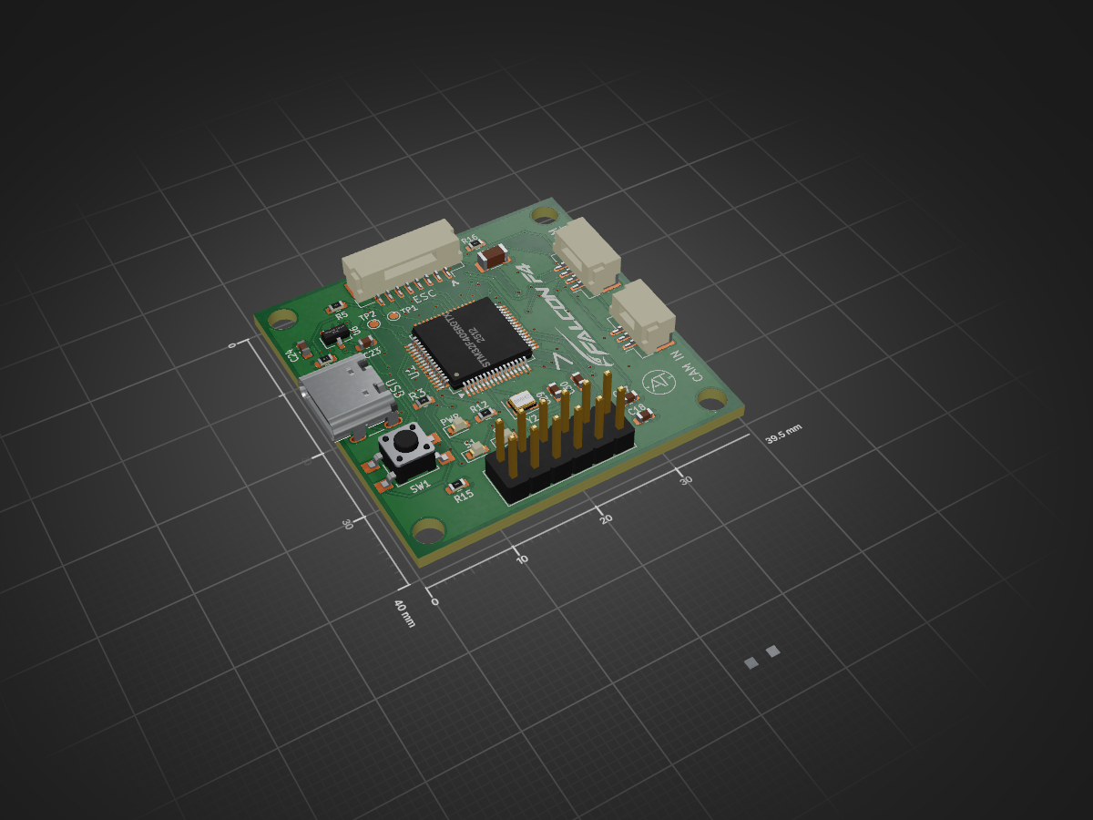
Falcon F4-Flight controller is an open-source printed circuit board by AT882, from the AT882/Falcon-F4-Flight-controller repository on GitHub. It is a 4-layer board of 39.5 × 40 mm with 76 parts on 102 nets, routed with 760 tracks and 137 vias.
It is built around the AT7456E, BMP388 and TPS54202DDC, with the W25Q128JVPIQ and ICM-42688-V among its other parts. Its parts include 30 capacitors, 19 resistors, 7 ICs, 3 switches and 2 crystals. It belongs with the robots and motor control boards and the STM32 boards of this library.


Custom STM32F405-based flight controller designed for UAV, FPV and aerial robotics applications.
The Falcon F4 Flight Controller is a custom-designed flight-control board based on the STM32F405RGT6 ARM Cortex-M4 microcontroller.
The board integrates the core hardware required for a compact UAV flight-control system, including a 6-axis IMU, barometric pressure sensor, analog video OSD, external SPI Flash memory, regulated power supplies, battery-voltage monitoring, current sensing, ESC interfaces, camera and VTX interfaces, USB connectivity and SWD debugging.
The complete electrical schematic is provided in this repository along with images of the designed PCB.
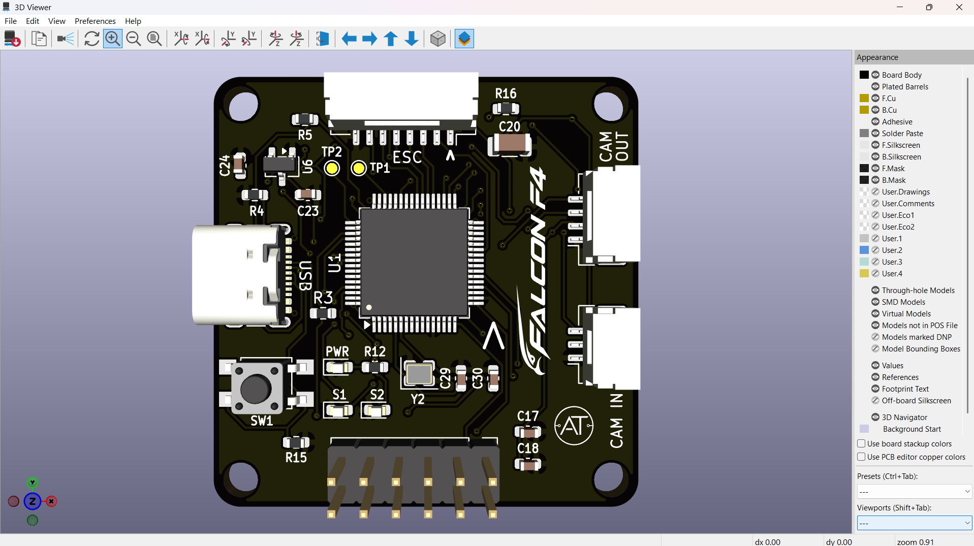
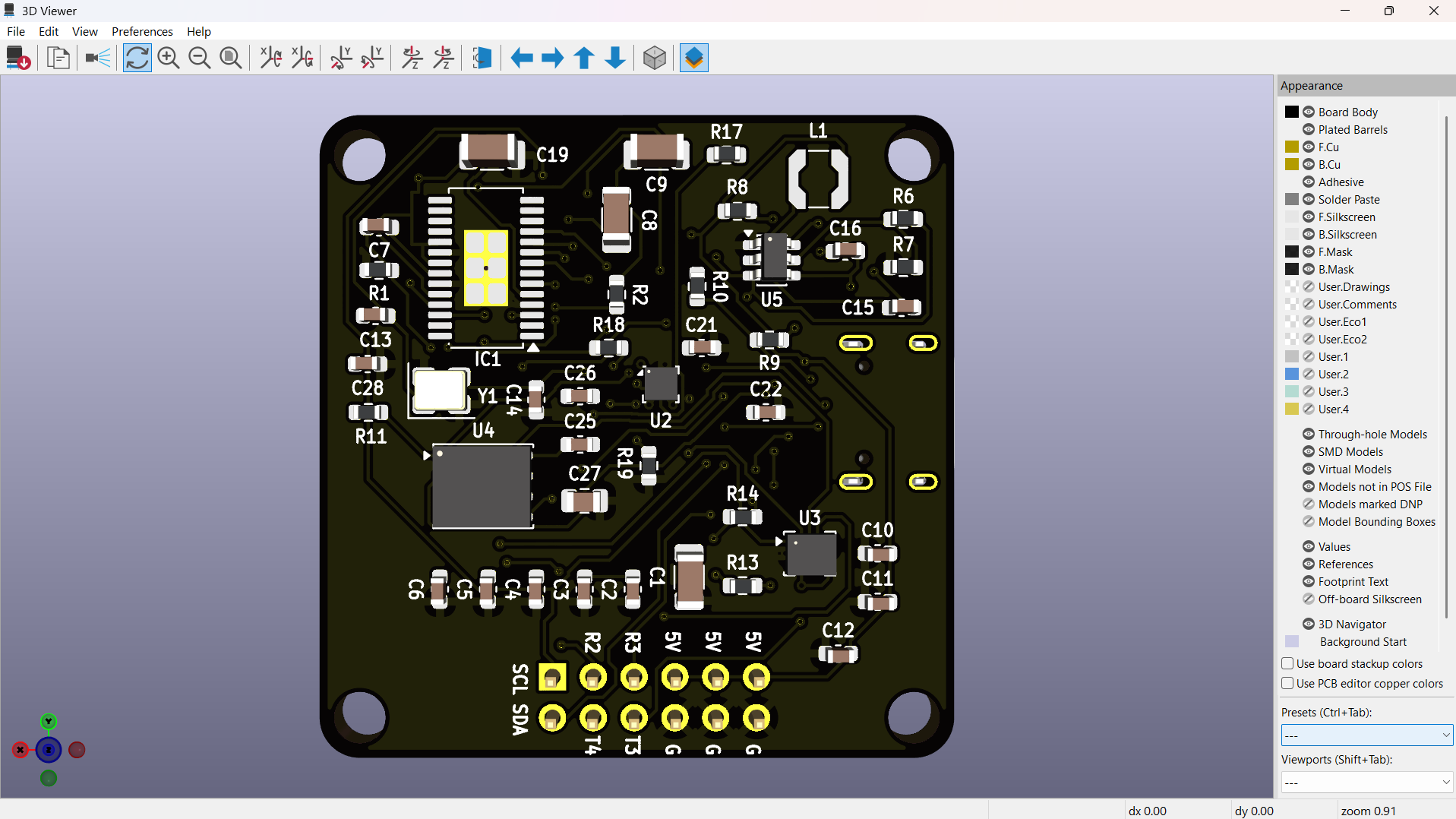
The STM32F405RGT6 is the main processing unit of the Falcon F4.
It provides the processing capability required for real-time flight-control applications and interfaces with the onboard sensors, memory, OSD circuitry, external peripherals and flight-control interfaces.
The MCU provides connections for:
The ICM-42688-P is used as the primary inertial measurement unit.
It provides:
The IMU is connected to the STM32 through an SPI interface.
The main IMU signals are:
SPI1_SCK
SPI1_MISO
SPI1_MOSI
IMU_CS
The IMU has local decoupling capacitors to provide a stable supply and reduce supply noise.
The sensor provides motion information required for:
The BMP388 is used for barometric pressure and altitude measurement.
The sensor is connected to the STM32 through the I²C interface.
The primary signals are:
I2C1_SCL
I2C1_SDA
The barometer can be used for:
The AT7456E is used as the analog video OSD controller.
The OSD section allows flight information to be overlaid onto the analog video stream.
The video path is:
Camera
   |
   v
AV_IN
   |
   v
AT7456E
   |
   v
AV_OUT
   |
   v
VTX
The OSD section includes a dedicated 27 MHz crystal and associated circuitry.
Possible OSD information includes:
The W25Q128JV is a 128-Mbit SPI NOR Flash memory device.
The external Flash provides non-volatile memory for storing application data.
Potential uses include:
The Flash interface uses:
FLASH_CS
SPI3_SCK
SPI3_MISO
SPI3_MOSIThe Falcon F4 contains dedicated power-management circuitry for generating the required voltage rails.
The main power architecture consists of:
+BATT
   |
   +------------------+
   |                  |
   v                  v
5 V Buck          Battery
Regulator         Monitoring
   |
   v
  5 V
   |
   v
3.3 V LDO
   |
   v
3.3 VThe TPS54202DDCR is used as the primary 5 V switching regulator.
The regulator converts the battery input into a regulated 5 V supply.
The regulator section includes:
The 5 V rail supplies the OSD/video section and other peripherals requiring 5 V.
The XC6206P332MR provides the 3.3 V supply rail.
The 3.3 V rail powers the main low-voltage digital and sensor circuitry, including:
Local decoupling capacitors are provided for the regulator and individual ICs.
The Falcon F4 includes an onboard battery-voltage sensing circuit.
A resistor-divider network scales the battery voltage to a suitable level for the STM32 ADC.
The schematic uses:
R18 = 20 kΩ
R19 = 1 kΩ
The scaled signal is connected to:
ADC_IN8This allows the flight-control firmware to monitor the connected battery voltage.
Battery-voltage monitoring can be used for:
A dedicated current-sense input is provided.
The signal is labelled:
CURRENTand is connected to the STM32 ADC system.
The current measurement can be used for:
The actual current-sensor implementation depends on the external ESC or power-monitoring hardware connected to the flight controller.
The Falcon F4 provides a dedicated multi-pin ESC interface.
The schematic includes:
ESC_S1
ESC_S2
ESC_S3
ESC_S4
ESC_S5
ESC_S6
ESC_TLM
CURRENT
+BATT
GND
The interface is intended to connect the flight controller to external electronic speed controllers.
The multiple ESC signal connections allow the board to be adapted for different multirotor configurations.
The ESC interface can be used for:
The exact communication protocol is determined by the flight-control firmware and connected ESC hardware.
A dedicated analog camera interface is provided.
The camera connector includes:
GND
+5V
AV_IN
The camera video signal is routed to the AT7456E OSD section.
The OSD then overlays flight information onto the video stream before sending it to the VTX.
A dedicated VTX connector is provided.
The interface includes:
GND
+BATT
AV_OUT
VTX_TBS
The processed analog video signal is available through:
AV_OUTThe VTX control signal can be used with compatible video transmitters and firmware.
The Falcon F4 includes a USB Type-C connector.
The USB section includes the required USB-C CC resistors and connections to the STM32.
The interface can be used for:
A dedicated Serial Wire Debug interface is provided for programming and debugging the STM32F405.
The primary SWD signals are:
SWDIO
SWCLK
The SWD interface can be used with an ST-LINK or compatible debugger.
It supports:
The board includes a dedicated boot-selection circuit.
The schematic provides:
BOOT
BOOT0
along with a boot switch and associated pull-down circuitry.
This allows the MCU boot configuration to be selected during development and firmware recovery.
The Falcon F4 includes onboard status and power indication LEDs.
The schematic contains:
LED1
LED2
POWER
These LEDs can be assigned by firmware to indicate:
The board contains dedicated clock sources for the MCU and OSD subsystem.
An 8 MHz crystal is provided for the STM32F405 clock system.
A separate 27 MHz crystal is provided for the AT7456E OSD controller.
Multiple SPI interfaces are used for high-speed peripheral communication.
The SPI interfaces are used for devices including:
The board provides an I²C interface for peripheral communication.
The primary signals are:
I2C1_SCL
I2C1_SDA
The onboard BMP388 is connected through this interface.
| Reference | Component | Function |
|---|---|---|
| U1 | STM32F405RGT6 | Main flight-controller MCU |
| U2 | BMP388 | Barometric pressure sensor |
| U3 | ICM-42688-P | 6-axis IMU |
| U4 | W25Q128JV | 128-Mbit SPI Flash |
| U5 | TPS54202DDCR | 5 V buck regulator |
| U6 | XC6206P332MR | 3.3 V LDO regulator |
| IC1 | AT7456E | Analog OSD controller |
| Y1 | 27 MHz crystal | OSD clock source |
| Y2 | 8 MHz crystal | MCU clock source |
| J1 | USB Type-C | USB interface |
| J2 | ESC connector | ESC interface |
| J3 | VTX connector | VTX interface |
| J4 | Camera connector | Camera interface |
| J5 | Auxiliary connector | External peripheral interface |
| SW1 | Boot switch | MCU boot selection |
The Falcon F4 is intended as a hardware platform for:
The complete electrical schematic is provided in this repository.
The schematic contains the major functional sections of the flight controller:
Falcon-F4-Flight-controller/
│
├── README.md
│
├── Schematic/
│   └── Falcon F4 Flightcontroller.kicad_sch
│
└── Images/
    ├── PCB FRONT VIEW.png
└── PCB BACK VIEW.pngCurrent project status:
Hardware schematic completed.
The PCB design has been developed as a custom flight-controller platform based on the STM32F405RGT6.
The repository currently contains the electrical schematic and PCB documentation images.
Further development may include PCB manufacturing files, bill of materials, assembly documentation and firmware.
Recommended hardware bring-up sequence:
Schematic Verification
        |
        v
PCB Fabrication
        |
        v
PCB Assembly
        |
        v
Visual Inspection
        |
        v
Power-Rail Verification
        |
        v
STM32 Programming
        |
        v
USB Verification
        |
        v
IMU Verification
        |
vInitial testing should verify:
This is a custom flight-controller hardware project.
The hardware should be thoroughly tested before installation on a flight-capable UAV.
Initial testing should be performed without propellers and with appropriate current limiting and laboratory power equipment.
Particular attention should be given to:
The Falcon F4 was designed around four primary objectives.
The STM32F405RGT6 provides a capable real-time processing platform suitable for UAV flight-control applications.
The board integrates inertial sensing, barometric sensing, OSD, external Flash memory and power regulation into a single custom flight-controller platform.
SPI, I²C, ADC, GPIO and dedicated external connectors provide flexibility for additional sensors, ESCs, cameras, VTX systems and peripherals.
USB, SWD and BOOT interfaces simplify firmware development, debugging and hardware testing.
| Parameter | Details |
|---|---|
| Project Name | Falcon F4 Flight Controller |
| MCU | STM32F405RGT6 |
| IMU | ICM-42688-P |
| Barometer | BMP388 |
| OSD | AT7456E |
| External Flash | W25Q128JV |
| 5 V Regulator | TPS54202DDCR |
| 3.3 V Regulator | XC6206P332MR |
| PCB Design Tool | KiCad |
| Application | UAV / FPV / Flight Control |
The licensing terms for the hardware design files and associated documentation will be specified as the project develops.
Falcon F4 Flight Controller
Custom STM32F405-based flight-control hardware platform for UAV, FPV and aerial robotics applications.
| Qty | Value | Footprint | References |
|---|---|---|---|
| 15 | 100nF | Capacitor_SMD:C_0603_1608Metric | C2, C3, C4, C5, C6, C7, C10, C11, C12, C15, C18, C21, C22, C25, C28 |
| 4 | 10pF | Capacitor_SMD:C_0603_1608Metric | C13, C14, C29, C30 |
| 4 | 1K | Resistor_SMD:R_0603_1608Metric | R12, R13, R14, R19 |
| 4 | 22uF | Capacitor_SMD:C_1206_3216Metric | C8, C9, C19, C20 |
| 4 | 5.1K | Resistor_SMD:R_0603_1608Metric | R3, R4, R16, R17 |
| 4 | MountingHole_3.2mm_M3 | MountingHole:MountingHole_3.2mm_M3 | H1, H2, H3, H4 |
| 2 | 10K | Resistor_SMD:R_0603_1608Metric | R11, R15 |
| 2 | 1uF | Capacitor_SMD:C_0603_1608Metric | C23, C24 |
| 2 | 75R | Resistor_SMD:R_0603_1608Metric | R1, R2 |
| 1 | 1.5K | Resistor_SMD:R_0603_1608Metric | R5 |
| 1 | 100K | Resistor_SMD:R_0603_1608Metric | R9 |
| 1 | 105K | Resistor_SMD:R_0603_1608Metric | R7 |
| 1 | 10nF | Capacitor_SMD:C_0603_1608Metric | C26 |
| 1 | 10uF | Capacitor_SMD:C_1206_3216Metric | C1 |
| 1 | 10uF | Capacitor_SMD:C_0603_1608Metric | C17 |
| 1 | 13.3K | Resistor_SMD:R_0603_1608Metric | R10 |
| 1 | 15uH | Inductor_SMD:L_Coilcraft_LPS3314 | L1 |
| 1 | 2.2uF | Capacitor_SMD:C_0805_2012Metric | C27 |
| 1 | 20K | Resistor_SMD:R_0603_1608Metric | R18 |
| 1 | 27Mhz | Crystal:Crystal_SMD_3225-4Pin_3.2x2.5mm | Y1 |
| 1 | 49.9R | Resistor_SMD:R_0603_1608Metric | R8 |
| 1 | 511K | Resistor_SMD:R_0603_1608Metric | R6 |
| 1 | 75pF | Capacitor_SMD:C_0603_1608Metric | C16 |
| 1 | 8Mhz | Crystal:Crystal_SMD_2520-4Pin_2.5x2.0mm | Y2 |
| 1 | AT7456E | Package_SO:TSSOP-28-1EP_4.4x9.7mm_P0.65mm_EP2.74x4.75mm | IC1 |
| 1 | BMP388 | Package_LGA:ST_HLGA-10_2x2mm_P0.5mm_LayoutBorder3x2y | U2 |
| 1 | BOOT | Button_Switch_SMD:SW_SPST_TL3305A | SW1 |
| 1 | CAM | Connector_JST:JST_GH_SM03B-GHS-TB_1x03-1MP_P1.25mm_Horizontal | CAM IN |
| 1 | CON | Connector_PinHeader_2.54mm:PinHeader_2x06_P2.54mm_Vertical | J5 |
| 1 | ESC | Connector_JST:JST_GH_SM08B-GHS-TB_1x08-1MP_P1.25mm_Horizontal | ESC |
| 1 | ICM-42688-V | Package_LGA:LGA-14_3x2.5mm_P0.5mm_LayoutBorder3x4y | U3 |
| 1 | LOGO | AT_Logo:falogo | G*** |
| 1 | LOGO | AT_Logo:ATlogo | G*** |
| 1 | POWER | LED_SMD:LED_0603_1608Metric | PWR |
| 1 | S1 | LED_SMD:LED_0603_1608Metric | S1 |
| 1 | S2 | LED_SMD:LED_0603_1608Metric | S2 |
| 1 | STM32F405RGTx | Package_QFP:LQFP-64_10x10mm_P0.5mm | U1 |
| 1 | SWCLK | TestPoint:TestPoint_Pad_D1.0mm | TP2 |
| 1 | SWDIO | TestPoint:TestPoint_Pad_D1.0mm | TP1 |
| 1 | TPS54202DDC | Package_TO_SOT_SMD:SOT-23-6 | U5 |
| 1 | USB_C_Receptacle_USB2.0_16P | Connector_USB:USB_C_Receptacle_GCT_USB4105-xx-A_16P_TopMnt_Horizontal | USB |
| 1 | VTX | Connector_JST:JST_GH_SM04B-GHS-TB_1x04-1MP_P1.25mm_Horizontal | CAM |
| 1 | W25Q128JVP | Package_SON:WSON-8-1EP_6x5mm_P1.27mm_EP3.4x4.3mm | U4 |
| 1 | XC6206PxxxMR | Package_TO_SOT_SMD:SOT-23-3 | U6 |


Federiconunezfrau/FCC-project-LARoptero
This repository contains the hardware for the Flight Control Computer of the LARoptero project


SlimeVR/SlimeVR-Tracker-nRF-PCB
SlimeNRF PCBs and 3D model files for cases and dock

rishikesh2715/STM32F7_FC
STM32F722RET6 Based Flight Controller with ICM-42688-P IMU, BMP388 Barometer, and much more!

bassammorsy/stm32-flight-controller
Custom 4-layer STM32F405RGTx quadcopter flight controller PCB designed in KiCad. Betaflight compatible, 4S–6S LiPo input, SMT assembled by JLCPCB.

ara-mkr/f405-flight-controller
This is a flight controller I designed as a side project. It was fun and pretty challenging, and I'm planning to build a drone with it at some point!
It measures 39.5 × 40 mm and has 4 copper layers, 1.6 mm thick.
76 parts, built around the AT7456E, BMP388, TPS54202DDC and W25Q128JVPIQ. The full list of its parts is on this page, with links to each part's symbol and footprint where PCBKit's library has them.
From the AT882/Falcon-F4-Flight-controller repository on GitHub, at the commit this page was made from: the board is Hardware Falcon F4/PCB/Falcon F4 Flightcontroller.kicad_pcb and its schematic Hardware Falcon F4/Schematic/Falcon F4 Flightcontroller.kicad_sch. PCBKit opens the board in the browser, with nothing to install.
Its repository states no licence, so its author keeps all rights: ask AT882 before reusing the design.