4 layers15.2 × 20.3 mm
StepStick DC Driver
ARCLille/StepStick-DC-Driver
A dual DC/H-bridge driver, designed as a drop-in replacement for a standard stepstick.
10 partsCERN-OHL-W-2.0
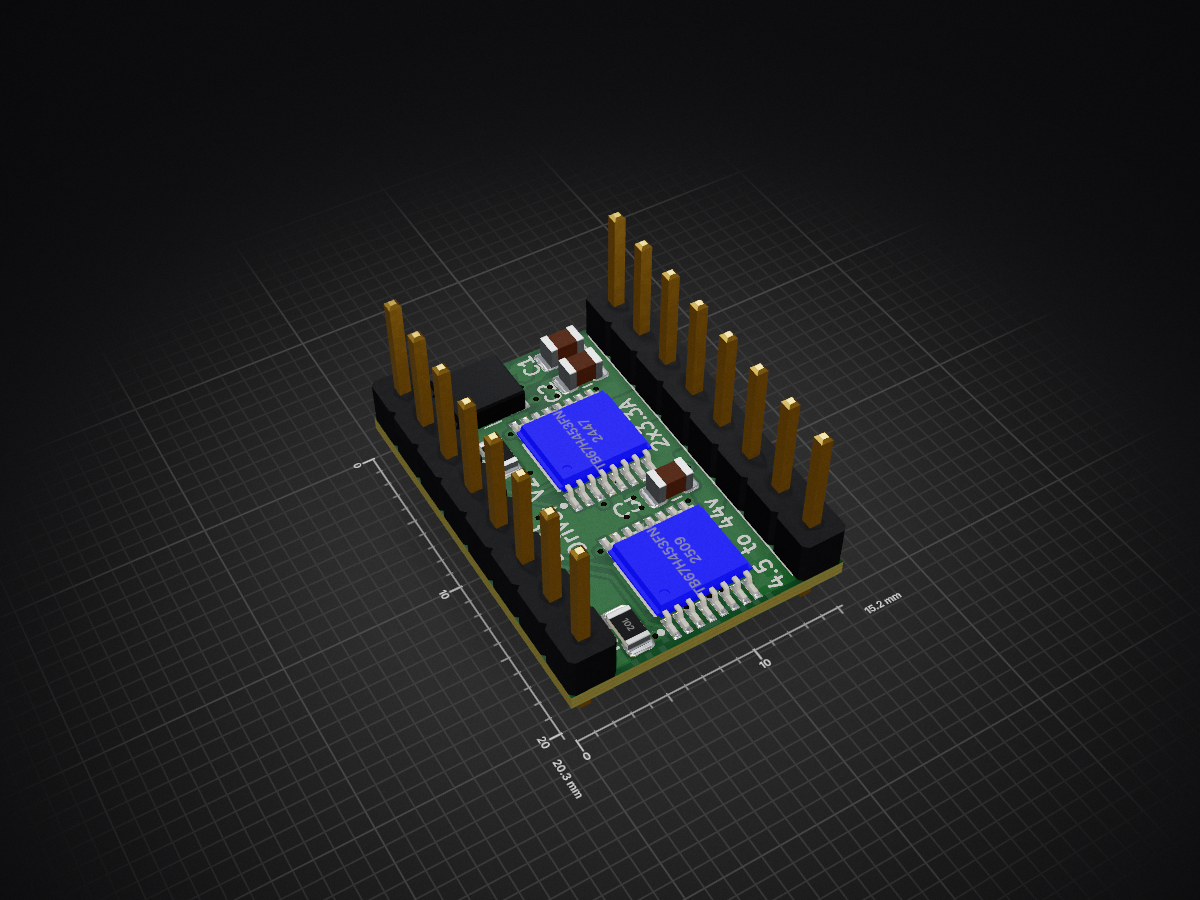
 ARCLille/StepStick-DC-Driver
A dual DC/H-bridge driver, designed as a drop-in replacement for a standard stepstick.
StepStick DC Driver is an open-source printed circuit board by ARCLille, from the ARCLille/StepStick-DC-Driver repository on GitHub, published under the CERN-OHL-W-2.0 licence. It is a 4-layer board of 15.2 × 20.3 mm with 10 parts on 26 nets, routed with 90 tracks and 69 vias.
It is built around the TB67H453FNG(O,EL). Its parts include 3 capacitors, 2 resistors, 2 ICs and 2 connectors.
A dual DC/H-bridge driver, designed as a drop-in replacement for a standard stepstick.
Designed around the TB67H481FNG IC. Datasheets can be found here.
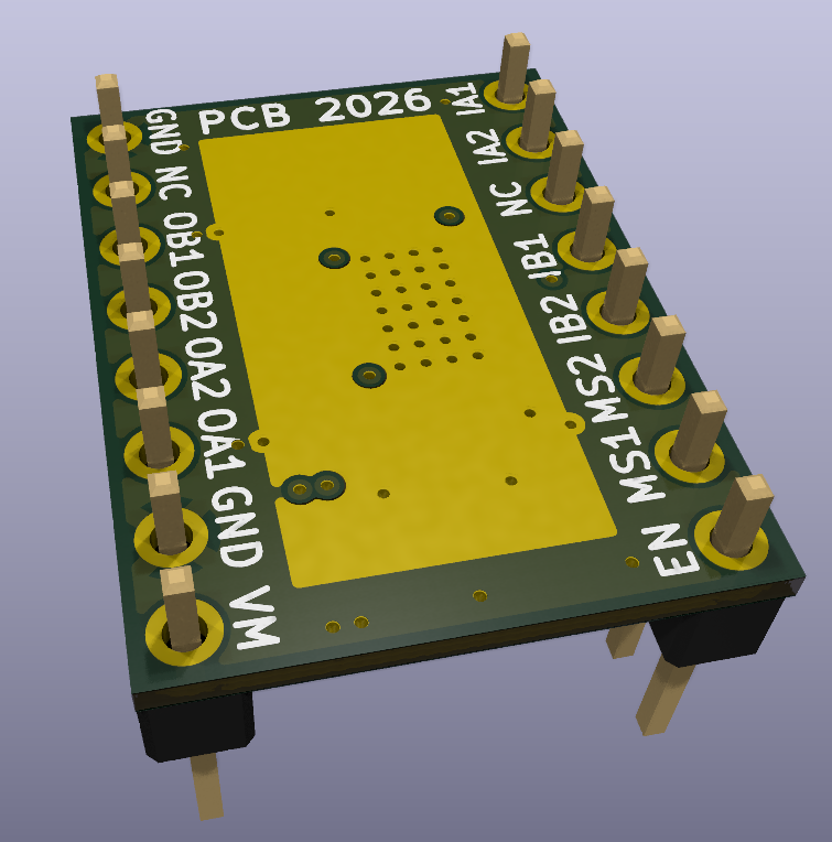
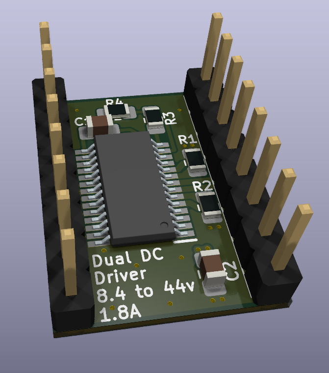
MS1 and MS2 pinsen pin, just like a standard stepstick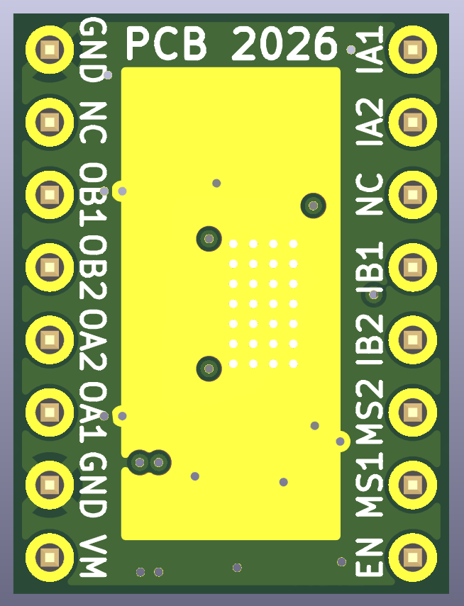
You can use the Pololu_Breakout_A4988 symbol from the default KiCad library, with its accompanying default footprint. Here is a pinout correspondence for the pins :
| StepStick DC Driver | Pololu A4988 |
|---|---|
| OB1 | 1B |
| OB2 | 1A |
| OA2 | 2A |
| OA1 | 2B |
| IA1 | DIR |
| IA2 | STEP |
| IB1 | RESET |
| IB2 | MS3 |
| NC | VDD, SLEEP |
[!WARNING] You need to add a 100uf capacitor between the
VMandGNDpins.
If the resistors on the BOM are respected, the maximum intensity per channel can be configured with the MS1 and MS2 pins :
| MS1 | MS2 | Torque | Max current per channel |
|---|---|---|---|
| L | L | 100% | 1.8A |
| L | H | 71% | 1.3A |
| H | L | 38% | .7A |
| H | H | 0% (Output OFF) | 0A |
If left open, a pin will be pulled down (considered L). The configuration is the same for both channels.
Channel A and B are both controlled by their own two pins Ix1 and Ix2 :
| Ix1 | Ix2 | Ox1 | Ox2 | Mode |
|---|---|---|---|---|
| L | L | L | L | Short Brake |
| L | H | L | H | Counterclockwise |
| H | L | H | L | Clockwise |
| H | H | H | H | Short brake |
If left open, a pin will be pulled down (considered L). If you do not want to use one of the channels, you can simply not connect the output to anything.
The constraints have been set up for Aisler's Beautiful Boards service.
It is advised to use a .8mm total thickness instead of the standard 1.6mm to improve the thermal dissipation.
To be done.
| Qty | Value | Footprint | References |
|---|---|---|---|
| 3 | 1u | Capacitor_SMD:C_0805_2012Metric | C1, C2, C3 |
| 2 | 1k | Resistor_SMD:R_0805_2012Metric | R1, R2 |
| 2 | Conn_01x08_Pin | Connector_PinHeader_2.54mm:PinHeader_1x08_P2.54mm_Vertical | J1, J2 |
| 2 | TB67H453FNG | TB67H453FNG:TB67H453FNG | IC1, IC2 |
| 1 | R_Potentiometer_Trim 100k | POT_EVM3R:POT_EVM3R | RV1 |
ARCLille/StepStick-DC-Driver
A dual DC/H-bridge driver, designed as a drop-in replacement for a standard stepstick.


nanographs/Open-Beam-Interface
Just what you need to control the beam and get an image.


clydeshaffer/gametank
design files for the gametank hardware implementation

lukasloetkolben/OpenpilotHardware
Welcome to the Openpilot Hardware Collection!

COVESA/Open1722
Open-source implementation of the IEEE 1722 protocol, for streaming audio/video, tunneling CAN/LIN messages and enabling remote access to peripherals

system76/thelio-io-hardware
KiCad electrical design of Thelio Io board

It measures 15.2 × 20.3 mm and has 4 copper layers, 0.83 mm thick.
10 parts, built around the TB67H453FNG(O,EL). The full list of its parts is on this page, with links to each part's symbol and footprint where PCBKit's library has them.
From the ARCLille/StepStick-DC-Driver repository on GitHub, at the commit this page was made from: the board is StepStick DC Driver.kicad_pcb and its schematic StepStick DC Driver.kicad_sch. PCBKit opens the board in the browser, with nothing to install.
Its repository publishes it under the CERN-OHL-W-2.0 licence: you may reuse it on that licence's terms (keep the author's notice, and for a copyleft licence share your changes alike).