2 layers72 × 139 mm

 ALXCO-Hardware/squareboi58
The open hardware GB/GBC cartridge system
ATF1502BR is an open-source printed circuit board by ALXCO-Hardware, from the ALXCO-Hardware/squareboi repository on GitHub, published under the CC-BY-4.0 licence. It is a 2-layer board of 60 × 80 mm with 31 parts on 54 nets, routed with 327 tracks and 1 via.
Its parts include 10 resistors, 6 connectors, 4 capacitors, 3 diodes and 3 switches. It belongs with the retro computing and games boards and the FPGA and CPLD boards of this library.

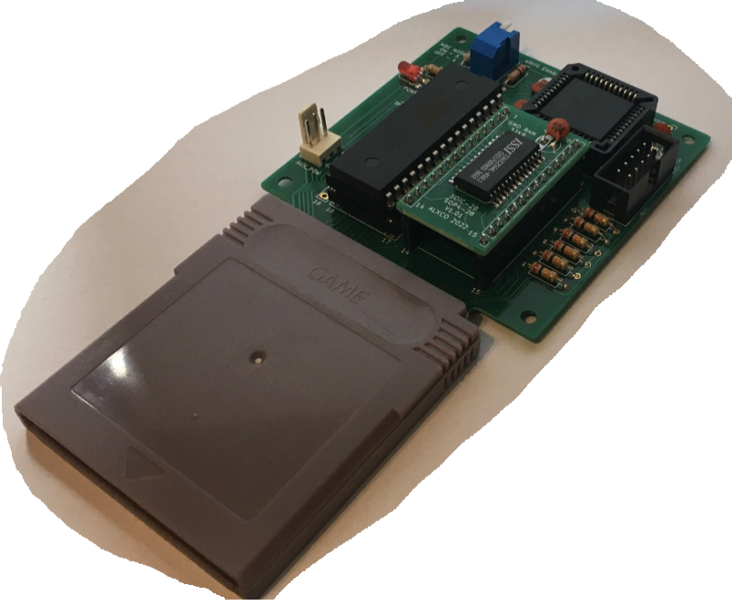
Squareboi is an open hardware cartridge system for the Game Boy Color, made to be as accessible and DIY-friendly as possible. Using a handful of off-the-shelf components, it provides the same functionality as an original cartridge, compatible with the majority of programs. Additionally, an Arduino-based programmer allows for easy transfer of games and save data.
Up to 4MB ROM/32KB RAM storage space
Stores save data without needing a battery
Made of common, off-the-shelf parts
Fully compatible with MBC1 and MBC5 mappers, partial support for MBC2 and MBC3
Programmer works as a general purpose cartridge reader
Easy to build: A basic version can be made with entirely through-hole components
Powered by a single 5V rail
Compatible with third-party programmers, like the widespread GBxCart RW
A thorough explanation of how the system works, and how to assemble it, can be found in the manual file, HERE.
Squareboi's existence is only possible due to the continued efforts of multiple individuals dedicated to reverse engineering and documenting the Game Boy hardware. A full list of those whose work I've built upon can be found within the manual.
Still, I'd like to say it again: Thanks to all of you! I wouldn't have gotten here alone.
Squareboi featured on Hackaday
Squareboi is the work of a hobbyist – And while significant care was taken to make it reliable, I cannot guarantee that it will work in your specific use case, or that it will be compatible with your hardware.
Squareboi is licensed under the Creative Commons Attribution 4.0 International License (CC BY 4.0). https://creativecommons.org/licenses/by/4.0/#deed-conditions
In essence, if you share or adapt this work, you must credit the author (ALXCO), and provide a link to the Squareboi repository, at: https://github.com/ALXCO-Hardware/squareboi
| Qty | Value | Footprint | References |
|---|---|---|---|
| 10 | 10K | Resistor_THT:R_Axial_DIN0207_L6.3mm_D2.5mm_P7.62mm_Horizontal | R1, R2, R3, R4, R5, R12, R13, R14, R15, R16 |
| 4 | 220nF | Capacitor_THT:CP_Radial_D5.0mm_P2.50mm | C1, C2, C3, C4 |
| 3 | LED | LED_THT:LED_D3.0mm | D0, D1, D8 |
| 2 | Conn_01x22 | Connector_PinHeader_2.54mm:PinHeader_1x22_P2.54mm_Vertical | J3, J5 |
| 2 | SW_Push | Button_Switch_THT:SW_PUSH_6mm_H5mm | SW4, SW5 |
| 1 | ATF1502-PLCC | Package_LCC:PLCC-44_THT-Socket | U1 |
| 1 | Conn_01x02 | Connector_PinHeader_2.54mm:PinHeader_1x02_P2.54mm_Vertical | J2 |
| 1 | Conn_02x05_Odd_Even | Connector_PinHeader_2.54mm:PinHeader_2x03_P2.54mm_Vertical | J6 |
| 1 | Conn_02x05_Odd_Even | Connector_PinHeader_2.54mm:PinHeader_2x05_P2.54mm_Vertical | J4 |
| 1 | SW_DIP_x06 | Button_Switch_THT:SW_DIP_SPSTx06_Slide_9.78x17.42mm_W7.62mm_P2.54mm | SW1 |
| 1 | USB_B | Connector_USB:USB_B_Lumberg_2411_02_Horizontal | J1 |
The 27 most common of 31 parts.


joeycastillo/Sensor-Watch
A board replacement for the classic Casio F-91W wristwatch

hoglet67/RGBtoHDMI
Bare-metal Raspberry Pi project that provides pixel-perfect sampling of Retro Computer RGB/YUV video and conversion to HDMI

hackclub/OnBoard
💡 Join 1,000 teenagers and make your first PCB with a $100 grant!

openwch/ch32v003
CH32V003 is an ultra-cheap RISC-V MCU with 2KB SRAM, 16KB flash, and up to 18 GPIOs that sells for under $0.10

Luos-io/luos_engine
Open-source and real-time orchestrator for cyber-physical-systems, to easily design, test and deploy embedded applications and digital twins.

BlueAndi/Pixelix
Full RGB LED matrix, based on an ESP32 and WS2812B LEDs or emulated LEDs on TFT.


It measures 60 × 80 mm and has 2 copper layers, 1.6 mm thick.
31 parts. The full list of its parts is on this page, with links to each part's symbol and footprint where PCBKit's library has them.
From the ALXCO-Hardware/squareboi repository on GitHub, at the commit this page was made from: the board is Hardware/KiCad 6/ATF Devboard/ATF1502BR.kicad_pcb and its schematic Hardware/KiCad 6/ATF Devboard/ATF1502BR.kicad_sch. PCBKit opens the board in the browser, with nothing to install.
Its repository publishes it under the CC-BY-4.0 licence: you may reuse it on that licence's terms (keep the author's notice, and for a copyleft licence share your changes alike).