4 layers81 × 60 mm
AOS16 GPU
AJain9199/AOS16
Table of Contents About The Project Pictures Technical Details Directory Structure To-Do Acknowledgments
118 parts1

 AJain9199/AOS161
Table of Contents About The Project Pictures Technical Details Directory Structure To-Do Acknowledgments
Control is an open-source printed circuit board by AJain9199, from the AJain9199/AOS16 repository on GitHub. It is a 4-layer board of 90 × 88 mm with 129 parts on 158 nets, routed with 1,248 tracks and 101 vias.
It is built around the 74AHC1G08GW, 74AHC1G32GW and 74AHC1G04SE, with the 74HC173D, 74AHC1G00GW and 74LS157PC among its other parts. Its parts include 32 resistors, 32 diodes, 24 capacitors, 21 ICs and 12 connectors.


[blocked]
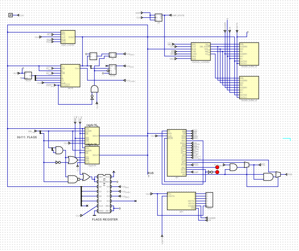
A self-made 16-bit computer.
AOS16 is a self-made 16-bit Reduced Instruction Set Computer (RISC) on PCBs, complete with a homebrew GPU for screen output. It is fully planned, designed and fabricated from scratch. A Turing-complete, Harvard-style computer with a completely custom architecture, at a blistering fast 10MHz.
The project is divided into smaller subsytems on PCBs, designed to interconnect via a central bus.
This project was a learning effort for me. I started this project wanting to learn more about computer architectures and gain hands-on experience with electrical engineering. Also, building a computer, from scratch, is the coolest project I've seen around. Some inspiration from amazing engineers including Ben Eater and jdh were more than enough to convince me to try my hand at this project.
Most homebrew computers on the internet are 8-bit computers built on breadboards. AOS16 is novel in its capabilities, being a 16-bit computer built on PCBs with a much higher clock speed, with display support directly integrated.
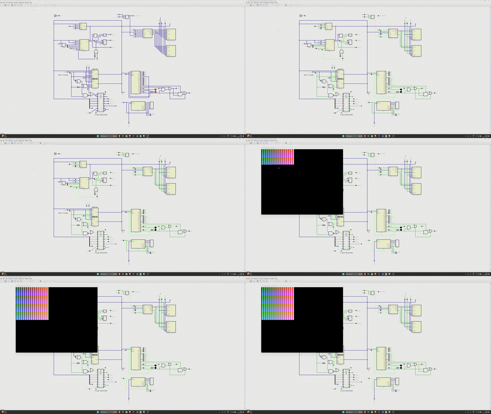
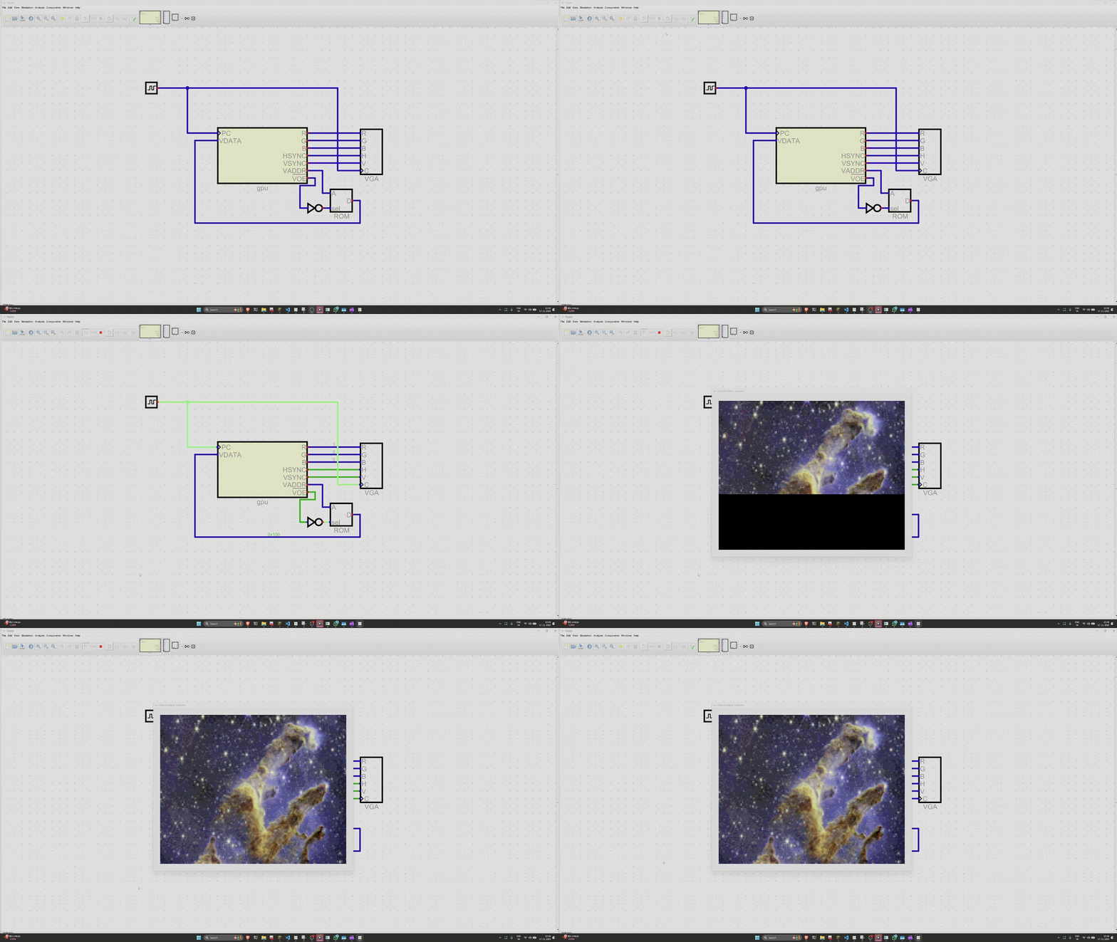
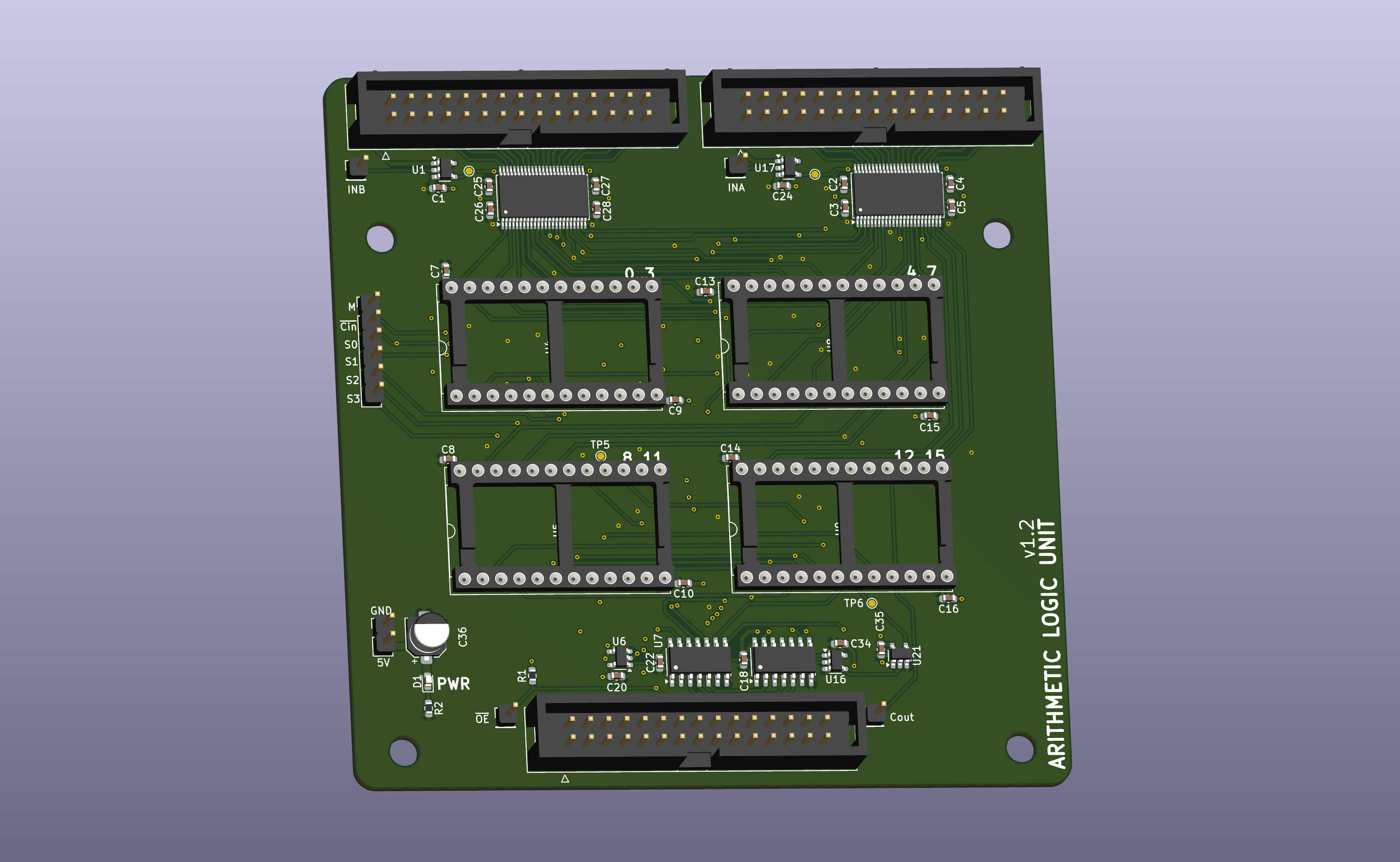
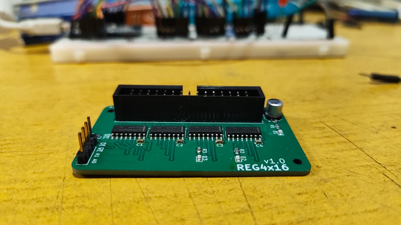
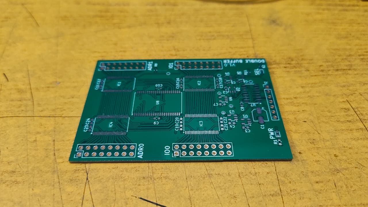
Details about the design decisions, design of the instruction word, etc. can be found in the Design Doc.
Each of the remaining folders represents a subsystem, built on a separate PCB. Each folder will contain a KiCAD schematic and PCB file.
Main Phases of the project:
| Component / Phase | Logic Simulation | PCB Design | Fabrication and Integration |
|---|---|---|---|
| Double Buffer | ✅ | ✅ | ✅ |
| Memory Controller | ✅ | ✅ | ✅ |
| ALU | ✅ | ✅ | ✅ |
| Registers | ✅ | ✅ | ✅ |
| Control Unit | ✅ | ✅ | ✅ |
| Program Counter | ✅ | ✅ | ☐ |
| GPU | ✅ | ✅ | ☐ |
| Main Data Bus | ✅ | ✅ | ☐ |
| Phase Completed | ✅ | ✅ | ☐ |
| Qty | Value | Footprint | References |
|---|---|---|---|
| 32 | 220 | Resistor_SMD:R_0603_1608Metric | R1, R2, R10, R11, R12, R13, R14, R15, R16, R17, R18, R19, R20, R21, R22, R23 +16 |
| 32 | LED_Small | LED_SMD:LED_0603_1608Metric | D1, D2, D10, D11, D12, D13, D14, D15, D16, D17, D18, D19, D20, D21, D22, D23 +16 |
| 20 | 0.1uF | Capacitor_SMD:C_0603_1608Metric | C1, C2, C3, C12, C13, C14, C15, C16, C17, C18, C19, C20, C21, C22, C23, C24 +4 |
| 8 | TestPoint | TestPoint:TestPoint_Pad_D1.0mm | TP1, TP2, TP3, TP4, TP5, TP6, TP7, TP8 |
| 5 | Conn_01x02 | Connector_PinHeader_2.54mm:PinHeader_1x02_P2.54mm_Vertical | J6, J7, J9, J10, J11 |
| 4 | 0.01uF | Capacitor_SMD:C_0603_1608Metric | C8, C9, C10, C11 |
| 4 | 74AHC1G08 | Package_TO_SOT_SMD:SOT-23-5 | U9, U10, U20, U21 |
| 4 | SST39SF020 | Package_DIP:DIP-32_W15.24mm_Socket | U4, U5, U6, U7 |
| 3 | 74AHC1G32 | Package_TO_SOT_SMD:SOT-23-5 | U12, U14, U18 |
| 2 | 4078 | Package_SO:SOIC-14_3.9x8.7mm_P1.27mm | U16, U17 |
| 2 | 74AHC1G04 | Package_TO_SOT_SMD:SOT-23-5 | U1, U11 |
| 2 | 74HC173 | Package_SO:SOIC-16_3.9x9.9mm_P1.27mm | U15, U19 |
| 2 | Conn_01x04 | Connector_PinSocket_2.54mm:PinSocket_1x04_P2.54mm_Vertical | J5, J8 |
| 2 | Conn_02x08_Odd_Even | Connector_PinHeader_2.54mm:PinHeader_2x08_P2.54mm_Vertical | J1, J2 |
| 1 | 74AHC1G00 | Package_TO_SOT_SMD:SOT-23-5 | U13 |
| 1 | 74LS157 | Package_SO:SOIC-16_3.9x9.9mm_P1.27mm | U22 |
| 1 | 74LS161 | Package_SO:SOIC-16_3.9x9.9mm_P1.27mm | U3 |
| 1 | Conn_01x01 | Connector_PinHeader_2.54mm:PinHeader_1x01_P2.54mm_Vertical | J12 |
| 1 | Conn_02x15_Odd_Even | Connector_IDC:IDC-Header_2x15_P2.54mm_Vertical | J3 |
| 1 | MCR-MCRI | Connector_PinHeader_2.54mm:PinHeader_1x02_P2.54mm_Vertical | J4 |
| 1 | SN74AHCT16374DGGR | Package_SO:TSSOP-48_6.1x12.5mm_P0.5mm | U8 |
AJain9199/AOS16
Table of Contents About The Project Pictures Technical Details Directory Structure To-Do Acknowledgments

AJain9199/AOS16
Table of Contents About The Project Pictures Technical Details Directory Structure To-Do Acknowledgments

AJain9199/AOS16
Table of Contents About The Project Pictures Technical Details Directory Structure To-Do Acknowledgments

AJain9199/AOS16
Table of Contents About The Project Pictures Technical Details Directory Structure To-Do Acknowledgments

AJain9199/AOS16
Table of Contents About The Project Pictures Technical Details Directory Structure To-Do Acknowledgments

AJain9199/AOS16
Table of Contents About The Project Pictures Technical Details Directory Structure To-Do Acknowledgments

AJain9199/AOS16
Table of Contents About The Project Pictures Technical Details Directory Structure To-Do Acknowledgments

AJain9199/AOS16
Table of Contents About The Project Pictures Technical Details Directory Structure To-Do Acknowledgments

AJain9199/AOS16
Table of Contents About The Project Pictures Technical Details Directory Structure To-Do Acknowledgments

AJain9199/AOS16
Table of Contents About The Project Pictures Technical Details Directory Structure To-Do Acknowledgments

AJain9199/AOS16
Table of Contents About The Project Pictures Technical Details Directory Structure To-Do Acknowledgments

AJain9199/AOS16
Table of Contents About The Project Pictures Technical Details Directory Structure To-Do Acknowledgments

MelonMars/TuringPCB
A Turing Machine that does not use any premade microchips, but rather is built exclusively on simple components.


jerry-kerenzikov/ytterbium
Project files for Ytterbium modular CPU platform and Yprog programming tool

elixpo/elixpo_chapter
Elixpo’s canonical collection for public build-and-release Chapters, bringing open-source software, reproducible research, hardware, and community contributions into one attributable record.


moi-script/pcb_ui
A simple one-layer PCB "drawer": read a KiCad board, extract the copper traces, and turn them into travel-optimized G-code you can plot on a pen-plotter / small CNC driven by a microcontroller (GRBL — an Arduino running…

EOSCogniton/ELIZ-2022
Le Git Artemiz de l'EPSA. Contient le Catia, ainsi que la documentation en cours et quelques modèles.

It measures 90 × 88 mm and has 4 copper layers, 1.6 mm thick.
129 parts, built around the 74AHC1G08GW, 74AHC1G32GW, 74AHC1G04SE and 74HC173D. The full list of its parts is on this page, with links to each part's symbol and footprint where PCBKit's library has them.
From the AJain9199/AOS16 repository on GitHub, at the commit this page was made from: the board is Control/Control.kicad_pcb and its schematic ALU/ALU.kicad_sch. PCBKit opens the board in the browser, with nothing to install.
Its repository states no licence, so its author keeps all rights: ask AJain9199 before reusing the design.