2 layers65 × 30 mm
Pi zero serial hat
aqualinkd/aqualinkd-zero-hat
Raspberry HAT to provide RS485 I/O and Power from Jandy RS485 control panel.
45 parts6

 8aChristian/InduLink-485
The board follows rigorous IPC (IPC-2152, IPC-2221, IPC-7351) standards, complete with galvanic isolation, industrial transient protection (TVS, Schottky, PTC Polyfuse), a wide-input step-down switching power…
InduLink-485 is an open-source printed circuit board by 8aChristian, from the 8aChristian/InduLink-485 repository on GitHub, published under the MIT licence. It is a 4-layer board of 115 × 75 mm with 24 parts on 24 nets, routed with 332 tracks and 53 vias.
It is built around the B0505S-1WR3, ESP32-S3-WROOM-1-N8R8 and MAX13487EESA+, with the SIM7080G, AP2112K-3.3TRG1 and ISO7721DWR among its other parts. Its parts include 7 ICs, 5 diodes, 4 connectors, 2 capacitors and 1 inductor. It belongs with the ESP32 boards of this library.



 [blocked]
 [blocked]
 [blocked]
 [blocked]

InduLink-485 is a rugged, industrial-grade IoT gateway and telemetry edge node designed for mission-critical industrial automation, SCADA networks, PLC monitoring, and remote field deployments. Built around the high-performance Espressif ESP32-S3 dual-core microcontroller and the SIMCom SIM7080G multi-band cellular modem, it delivers robust, isolated bidirectional RS-485 / Modbus RTU communication with dual-link connectivity over global LTE-M, NB-IoT, Wi-Fi, and Bluetooth Low Energy.
The board follows rigorous IPC (IPC-2152, IPC-2221, IPC-7351) standards, complete with galvanic isolation, industrial transient protection (TVS, Schottky, PTC Polyfuse), a wide-input step-down switching power architecture (9V–36V), and an optimized 4-layer controlled-impedance stackup.
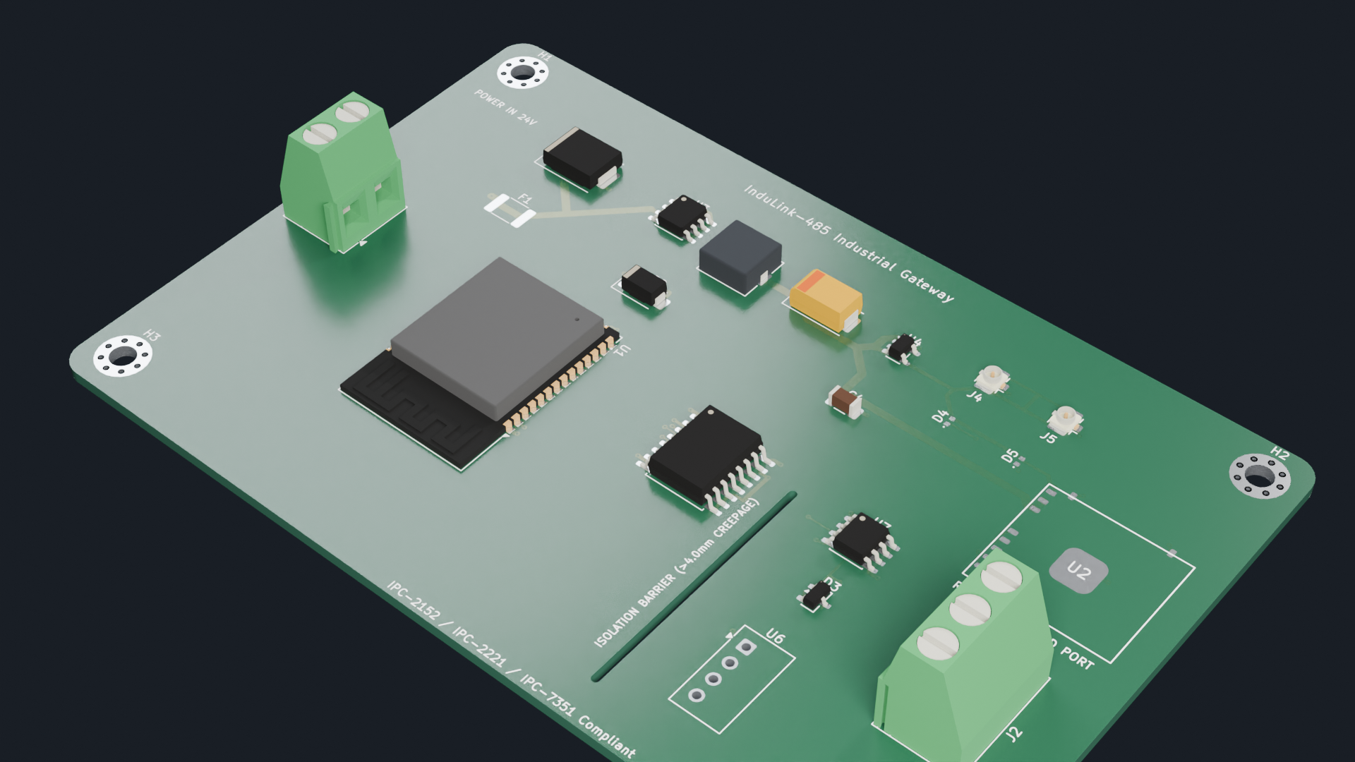
Figure 1: High-Fidelity 3D Isometric Photorealistic Render of the InduLink-485 Industrial Gateway PCBA.
The board features a high-density 4-layer architecture with dedicated signal, power, and ground planes. Below is the visual breakdown of every individual fabrication layer:
F.Cu) & Bottom Layer (L4 - B.Cu)Layer 1: Top Copper & Silkscreen (F.Cu) | Layer 4: Bottom Copper & Silkscreen (B.Cu) |
|---|---|
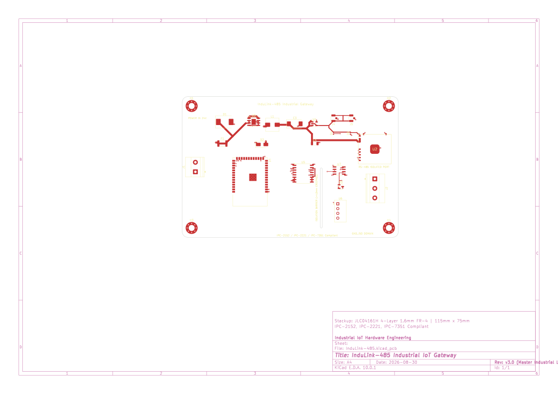 | 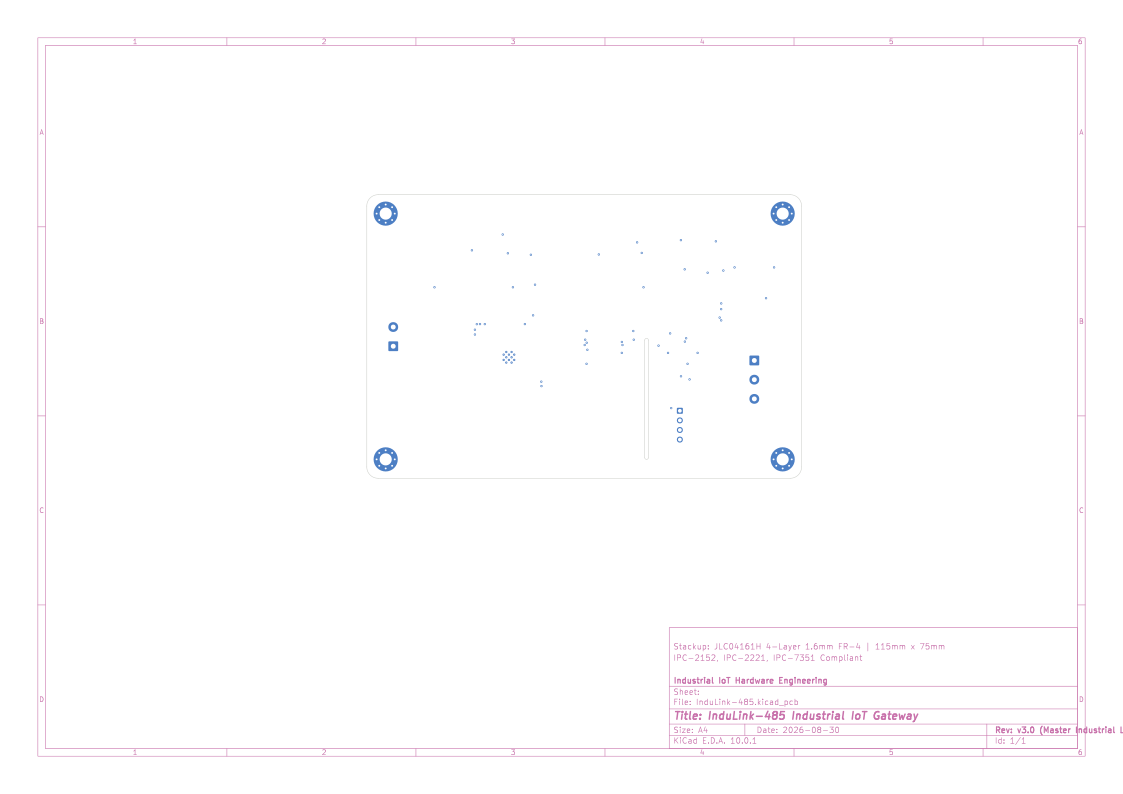 |
| High-speed signals, 50Ω RF coplanar microstrips, Buck power loop, SMD pads | Secondary digital routing, control lines, and bottom ground shield |
In1.Cu GND & L3 - In2.Cu Power)Layer 2: Solid Ground Plane (In1.Cu) | Layer 3: Power Distribution Planes (In2.Cu) |
|---|---|
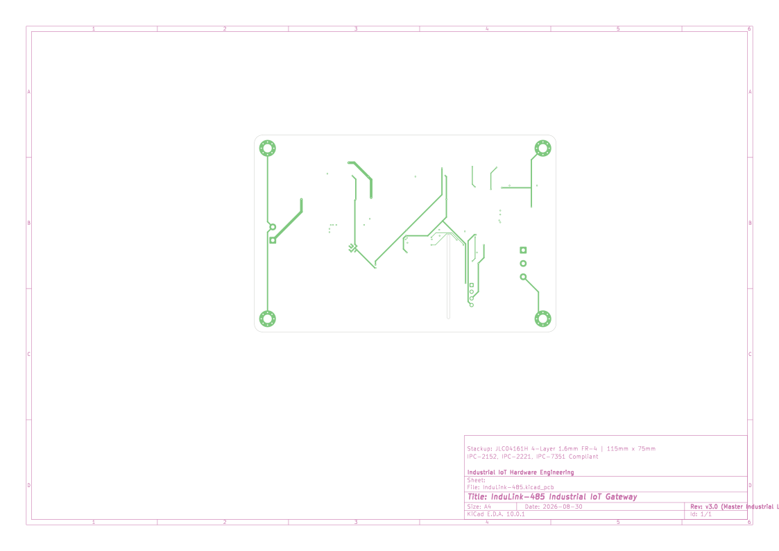 | 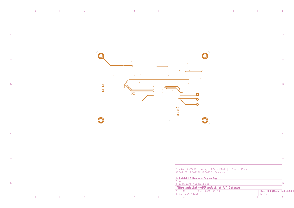 |
| 100% Continuous low-impedance ground reference plane (Zero slots) | Partitioned power planes (+3.8V GSM bus, +3.3V system rail, +5V_ISO) |
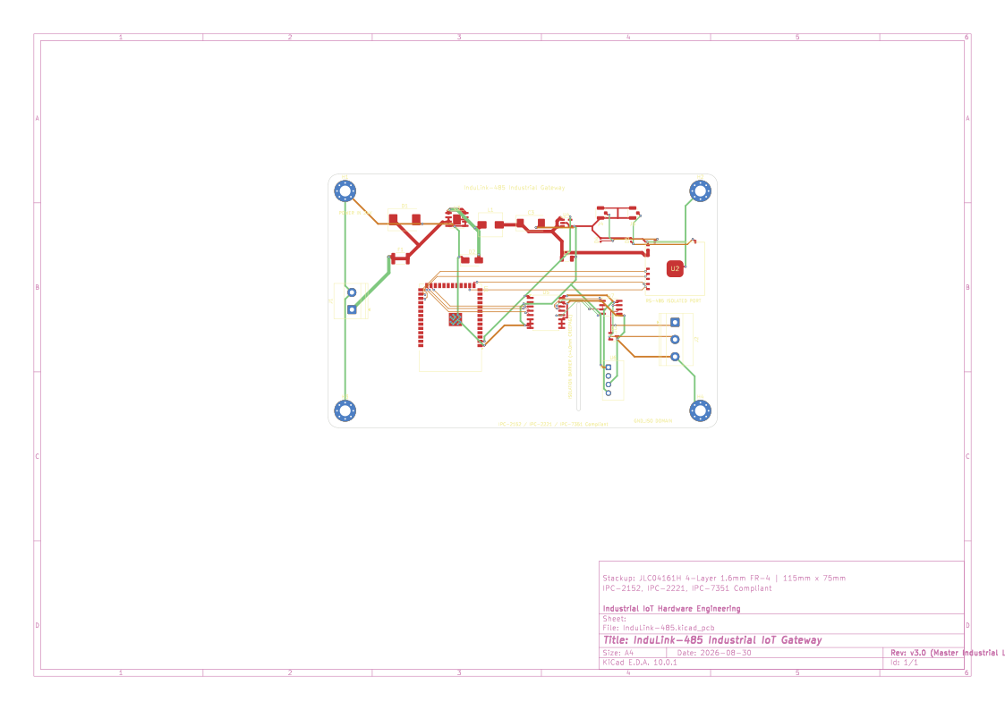
| 4-Layer Multilayer X-Ray View | Complete Circuit Schematic |
|---|---|
 | 📄 Download Schematic PDF  |
| All 4 copper layers combined with Edge.Cuts & isolation barrier | Full hierarchical schematic capture with multi-domain protection |
📁 3D CAD & Documentation: 3D models are available in
docs/3d/InduLink-485.stepanddocs/3d/InduLink-485.glb. Manufacturing packages reside infabrication/.
graph TD
    subgraph Power_Stage ["⚡ Industrial Power Architecture (9V - 36V DC)"]
        VIN["DC Power In (9V - 36V, 24V Typ)"] --> PROT["TVS SMCJ33CA + PTC Fuse 750mA + Reverse Polarity Diode"]
        PROT --> BUCK["LMR14030 Buck Converter (3.8V / 3.5A Peak)"]
        BUCK --> LDO["AP2112K-3.3 Ultra-Low Noise LDO (3.3V / 600mA)"]
        BUCK --> POSCAP["1000uF POSCAP Polymer Buffer (GSM 2A Burst Support)"]
        BUCK --> ISODC["B0505S-1WR3 Isolated DC-DC (5V_ISO Domain)"]
    end

    subgraph Compute_RF ["🧠 Compute, Wireless & Cellular Core"]
        LDO --> ESP["ESP32-S3-WROOM-1 (Xtensa LX7 @ 240MHz, 8MB Flash/PSRAM)"]
        POSCAP --> MODEM["SIM7080G LTE-M / NB-IoT / GNSS Cellular Modem"]
        ESP <-->|UART High-Speed AT Bus| MODEM
        MODEM --> ANT_LTE["U.FL LTE-M Antenna (50Ω Coplanar)"]
        MODEM --> ANT_GNSS["U.FL GNSS Antenna (50Ω Active/Passive)"]
        ESP --> ANT_WIFI["ESP32 Integrated 2.4GHz PCB Antenna (Keep-Out Protected)"]
    end

    subgraph Isolated_Fieldbus ["🛡️ Galvanically Isolated RS-485 Fieldbus"]
        ESP <-->|Isolated TX/RX/DE Lines| ISO["TI ISO7721 High-Speed Digital Isolator (5kVrms, >8mm Creepage)"]
        ISODC --> ISO
        ISODC --> RS485_IC["MAX13487 AutoDirection RS-485 Transceiver"]
        ISO <--> RS485_IC
        RS485_IC --> ESD["Semtech SM712 Asymmetric TVS (+12V/-7V 30kV ESD)"]
        ESD --> TB_RS485["Phoenix Contact 3-Pin Terminal Block (A, B, GND_ISO)"]
end| Parameter | Specification | Engineering Details |
|---|---|---|
| Input Supply Voltage | $9.0 ext{V} - 36.0 ext{V DC}$ ($24 ext{V DC}$ Nominal) | Reverse polarity diode + $33 ext{V}$ 1500W TVS (SMCJ33CA) + 750mA PTC fuse (MF-MSMF075-2) |
| Main Step-Down Converter | TI LMR14030SDDAR ($3.8 ext{V} / 3.5 ext{A}$) | High-efficiency Eco-mode buck regulator with $10\mu ext{H}$ shielded power inductor (WE-HCI) |
| Cellular Transient Buffer | $1000\mu ext{F} ext{ POSCAP } + 100\mu ext{F} ext{ MLCC}$ | Ultra-low ESR ($10 ext{m}\Omega$) polymer tantalum capacitor for $<100 ext{mV}$ droop during $2 ext{A}$ LTE/GSM Tx bursts |
| Secondary Voltage Regulator | Diodes Inc AP2112K-3.3 ($3.3 ext{V} / 600 ext{mA}$) | High PSRR ($55 ext{dB}$), ultra-low dropout ($250 ext{mV}$) linear regulator for low-noise MCU core |
| Main Processing Unit (MCU) | Espressif ESP32-S3-WROOM-1-N8R8 | Dual-core Xtensa 32-bit LX7 @ 240MHz, 512KB SRAM, 8MB Quad SPI Flash, 8MB Octal PSRAM |
| Cellular & Satellite Subsystem | SIMCom SIM7080G Global Module | Multi-band LTE Cat-M1 (eMTC) & NB-IoT + Multi-Constellation GNSS (GPS, GLONASS, BeiDou, Galileo) |
| Wireless Connectivity | Wi-Fi 4 (802.11 b/g/n) & Bluetooth 5.0 (BLE) | Integrated PCB antenna with $100%$ copper-free keep-out zone on all 4 layers |
| Fieldbus Interface | Isolated Half-Duplex RS-485 / Modbus RTU | Maxim / ADI MAX13487EESA+ with proprietary AutoDirection control (no software RTS/DE switching required) |
| Galvanic Isolation Barrier | $5000 ext{V}_ ext{rms}$ Isolation / $100 ext{kV}/\mu ext{s}$ CMTI | TI ISO7721DWR wide-body isolator with a $1.0 ext{mm} imes 31.0 ext{mm}$ routed slot ($>4.0 ext{mm}$ physical creepage) |
| Isolated Power Supply | Mornsun B0505S-1WR3 ($1 ext{W} / 200 ext{mA}$) | $1.5 ext{kV DC}$ isolation between system ground (GND) and fieldbus ground (GND_ISO) |
| Operating Temperature | $-40^\circ ext{C} ext{ to } +85^\circ ext{C}$ (Industrial Grade) | All passive and active semiconductors derated $\ge 25%$ across full temperature envelope |
| Dimensions & Form Factor | $115.0 ext{ mm} imes 75.0 ext{ mm}$ ($R=3.0 ext{ mm}$ corners) | 4x M3 plated mechanical mounting holes with $\ge 6.5 ext{mm}$ isolation keep-outs |
The PCB is built on an industrial 4-Layer JLC04161H standard stackup ($1.6 ext{ mm}$ nominal thickness, $1 ext{ oz} / 35\mu ext{m}$ copper outer and inner layers):
========================================================================================
 Layer 1 (Top / F.Cu):        Component SMD Pads, 50Ω RF Coplanar Microstrips, Buck Power Loop
---------------------------------- Dielectric Prepreg (0.21mm, FR-4, Er=4.5) ----------------
 Layer 2 (Inner 1 / In1.Cu):  Solid Continuous Ground Plane (GND) - Zero Slots
---------------------------------- Core Dielectric (1.065mm, FR-4, Er=4.5) -----------------
 Layer 3 (Inner 2 / In2.Cu):  Power Planes & Rails (+3.8V_MODEM, +3.3V, +5V, +5V_ISO)
---------------------------------- Dielectric Prepreg (0.21mm, FR-4, Er=4.5) ----------------
 Layer 4 (Bottom / B.Cu):     Digital Control Signals & Secondary Ground Shield (B.Cu GND)
========================================================================================| Net Class Name | Target Nets | Track Width | Electrical Clearance | Via Rule (Dia / Drill) | Design Standard |
|---|---|---|---|---|---|
Power_HighCurrent | VIN, +3.8V_MODEM, SW_BUCK | $1.00 ext{ mm}$ ($40 ext{ mil}$) | $0.35 ext{ mm}$ ($14 ext{ mil}$) | $0.80 ext{ mm} / 0.40 ext{ mm}$ | IPC-2152 ($\Delta T < 10^\circ ext{C} @ 3.5 ext{A}$) |
Power_Standard | +3.3V, +5V, +5V_ISO | $0.50 ext{ mm}$ ($20 ext{ mil}$) | $0.25 ext{ mm}$ ($10 ext{ mil}$) | $0.60 ext{ mm} / 0.30 ext{ mm}$ | IPC-2152 ($1.5 ext{A}$ rated) |
GND_Planes | GND, GND_ISO | $0.50 ext{ mm}$ ($20 ext{ mil}$) | $0.25 ext{ mm}$ ($10 ext{ mil}$) | $0.60 ext{ mm} / 0.30 ext{ mm}$ | Low-impedance stitching |
RF_50R_Coplanar | LTE_ANT, GNSS_ANT | $0.35 ext{ mm}$ ($14 ext{ mil}$) | $0.20 ext{ mm}$ ($8 ext{ mil}$) | $0.60 ext{ mm} / 0.30 ext{ mm}$ | $50,\Omega$ Coplanar Waveguide w/ Ground |
RS485_Diff | RS485_A, RS485_B | $0.30 ext{ mm}$ ($12 ext{ mil}$) | $0.25 ext{ mm}$ (gap $0.25 ext{ mm}$) | $0.60 ext{ mm} / 0.30 ext{ mm}$ | $120,\Omega$ Differential Fieldbus |
Digital_Signals | ESP_*, MODEM_*, ISO_* | $0.20 ext{ mm}$ ($8 ext{ mil}$) | $0.20 ext{ mm}$ ($8 ext{ mil}$) | $0.60 ext{ mm} / 0.30 ext{ mm}$ | High-density 3.3V logic & UARTs |
| Item | Designator | Qty | Component / Value | Manufacturer | Manufacturer Part Number (MPN) | Package | Description |
|---|---|---|---|---|---|---|---|
| 1 | U1 | 1 | ESP32-S3-WROOM-1-N8R8 | Espressif Systems | ESP32-S3-WROOM-1-N8R8 | SMD-41 (18x25.5mm) | Dual-Core 240MHz MCU, Wi-Fi/BLE, 8MB Flash/PSRAM |
| 2 | U2 | 1 | SIM7080G | SIMCom Wireless | SIM7080G | LGA-78 (17.6x15.7mm) | Global LTE-M / NB-IoT / GNSS Positioning Modem |
| 3 | U3 | 1 | LMR14030SDDAR | Texas Instruments | LMR14030SDDAR | SOIC-8-PowerPAD | 4V-40V In, 3.5A Step-Down Buck Regulator |
| 4 | U4 | 1 | AP2112K-3.3TRG1 | Diodes Incorporated | AP2112K-3.3TRG1 | SOT-23-5 | Ultra-Low Dropout 3.3V / 600mA Linear Regulator |
| 5 | U5 | 1 | ISO7721DWR | Texas Instruments | ISO7721DWR | SOIC-16W (Wide Body) | 5kVrms High-Speed Digital Isolator (>8.0mm Creepage) |
| 6 | U6 | 1 | B0505S-1WR3 | Mornsun | B0505S-1WR3 | SIP-4 THT (11.6x6mm) | 1W Isolated 5V-to-5V DC-DC Converter (1.5kVDC) |
| 7 | U7 | 1 | MAX13487EESA+ | Analog Devices / Maxim | MAX13487EESA+ | SOIC-8 (3.9x4.9mm) | Half-Duplex RS-485 Transceiver w/ AutoDirection Control |
| 8 | D1 | 1 | SMCJ33CA | Littelfuse / Vishay | SMCJ33CA | DO-214AB (SMC) | 33V Vwm, 1500W Bidirectional TVS Surge Diode |
| 9 | D2 | 1 | B240A | Diodes Incorporated | B240A-13-F | DO-214AC (SMA) | 40V, 2.0A Schottky Rectifier (Low Vf = 0.50V) |
| 10 | D3 | 1 | SM712.TCT | Semtech | SM712.TCT | SOT-23 | Asymmetric Dual TVS (+12V/-7V) for RS-485 (30kV ESD) |
| 11 | D4, D5 | 2 | CD0402-T05C | Bourns | CD0402-T05C | 0402 (1005 Metric) | Ultra-Low Capacitance (0.5pF) 5V RF ESD Protection |
| 12 | F1 | 1 | MF-MSMF075-2 | Bourns | MF-MSMF075-2 | 1812 (4532 Metric) | Resettable PTC Fuse, 750mA Hold / 1.5A Trip, 30Vdc |
| 13 | C3 | 1 | 1000uF 6.3V POSCAP | Panasonic | 6TPB1000M | EIA-7343-31 (Case D) | Polymer Tantalum Capacitor, 10mΩ ESR (GSM Burst Buffer) |
| 14 | C4 | 1 | 100uF 10V X5R | Murata / TDK | GRM31CR61A107ME15L | 1206 (3216 Metric) | High-Capacitance Ceramic MLCC, 10V, ±20% |
| 15 | L1 | 1 | 10uH 3.5A Shielded | Würth Elektronik | 744314101 | SMD WE-HCI 7030 | High-Current Shielded Power Inductor (28mΩ DCR) |
| 16 | J1 | 1 | MKDS 1,5/ 2-5,08 | Phoenix Contact | 1715721 | Screw Terminal 2-Pin | 2-Pos 5.08mm Pitch Industrial Terminal (Power In) |
| 17 | J2 | 1 | MKDS 1,5/ 3-5,08 | Phoenix Contact | 1715734 | Screw Terminal 3-Pin | 3-Pos 5.08mm Pitch Industrial Terminal (RS-485 Port) |
| 18 | J4, J5 | 2 | U.FL-R-SMT-1 | Hirose Electric | U.FL-R-SMT-1(10) | U.FL SMT Vertical | Miniature 50Ω Coaxial RF Connectors (LTE & GNSS) |
| 19 | H1..H4 | 4 | M3 Mounting Hole | Standard Hardware | M3_Plated_3.2mm | M3 Pad Via Shielded | Plated M3 Mechanical Mounting Holes (GND Connected) |
InduLink-485/
├── docs/                               # Engineering documentation, CAD & schematics
│   ├── layers/                         # Individual high-resolution layer visualizations
│   │   ├── Layer1_Top_Copper.svg       # Layer 1 (F.Cu) + Silkscreen + Outlines
│   │   ├── Layer2_GND_Plane.svg        # Layer 2 (In1.Cu) Solid Ground Plane
│   │   ├── Layer3_Power_Plane.svg      # Layer 3 (In2.Cu) Power Distribution Rails
│   │   ├── Layer4_Bottom_Copper.svg    # Layer 4 (B.Cu) Bottom Signals + Silkscreen
│   │   └── All_Layers_Composite.svg    # 4-Layer full composite stackup view
│   ├── 3d/                             # 3D Mechanical CAD models
│   │   ├── InduLink-485.step           # Universal STEP 3D CAD Assembly
│   │   └── InduLink-485.glb            # Binary glTF 3D Web Visualization
│   ├── InduLink-485_Schematic.pdf      # Complete vector schematic PDF
│   ├── InduLink-485_PCB.pdf            # 4-Layer board fabrication drawing PDF
│   └── schematic/                      # Schematic sheet vector SVGs
├── fabrication/                        # Manufacturing & assembly packages
│   ├── gerbers/                        # RS-274X Gerber & Excellon Drill files
│   │   ├── InduLink-485-F_Cu.gtl       # Top Copper Layer
│   │   ├── InduLink-485-In1_Cu.g1      # Layer 2 Ground Plane
│   │   ├── InduLink-485-In2_Cu.g2      # Layer 3 Power Plane
│   │   ├── InduLink-485-B_Cu.gbl       # Bottom Copper Layer
│   │   ├── InduLink-485-F_Silkscreen.gto
│   │   ├── InduLink-485-F_Mask.gts
│   │   ├── InduLink-485-Edge_Cuts.gm1  # Board Outline & Milled Slots
│ │ └── InduLink-485-PTH.drl # Plated Through-Hole Drill Filegit clone https://github.com/8aChristian/InduLink-485.git
cd InduLink-485InduLink-485.kicad_pro inside KiCad.| Qty | Value | Footprint | References |
|---|---|---|---|
| 4 | M3_Hole | MountingHole_3.2mm_M3_Pad_Via | H1, H2, H3, H4 |
| 2 | CD0402-T05C | D_0402_1005Metric | D4, D5 |
| 1 | 1000uF_6.3V_POSCAP | CP_EIA-7343-31_Kemet-D | C3 |
| 1 | 100uF_10V | C_1206_3216Metric | C4 |
| 1 | 10uH_3.5A | L_Wuerth_HCI-7030 | L1 |
| 1 | AP2112K-3.3TRG1 | SOT-23-5 | U4 |
| 1 | B0505S-1WR3 | Converter_DCDC_TRACO_TME_03xxS_05xxS_12xxS_Single_THT | U6 |
| 1 | B240A | D_SMA | D2 |
| 1 | ESP32-S3-WROOM-1-N8R8 | ESP32-S3-WROOM-1 | U1 |
| 1 | GNSS_U.FL | U.FL_Hirose_U.FL-R-SMT-1_Vertical | J5 |
| 1 | ISO7721DWR | SOIC-16W_7.5x10.3mm_P1.27mm | U5 |
| 1 | LMR14030SDDAR | SOIC-8-1EP_3.9x4.9mm_P1.27mm_EP2.29x3mm | U3 |
| 1 | LTE_U.FL | U.FL_Hirose_U.FL-R-SMT-1_Vertical | J4 |
| 1 | MAX13487EESA+ | SOIC-8_3.9x4.9mm_P1.27mm | U7 |
| 1 | MF-MSMF075-2 | Fuse_1812_4532Metric | F1 |
| 1 | MKDS_1.5_2_5.08 | TerminalBlock_Phoenix_MKDS-1,5-2-5.08_1x02_P5.08mm_Horizontal | J1 |
| 1 | RS485_PORT | TerminalBlock_Phoenix_MKDS-1,5-3-5.08_1x03_P5.08mm_Horizontal | J2 |
| 1 | SIM7080G | SIMCom_SIM7080G | U2 |
| 1 | SM712.TCT | SOT-23 | D3 |
| 1 | SMCJ33CA | D_SMC | D1 |
aqualinkd/aqualinkd-zero-hat
Raspberry HAT to provide RS485 I/O and Power from Jandy RS485 control panel.

N5GEH/n5geh.devices.iot_wa_dio-
IoT-DIO is a wireless adapter for developing IoT applications for Industrial and Building Automation Systems based on the Espressif chipset ESP32. The adapter is compatible with: - RS485 - M-Bus - Ethernet

purpletue/TinyLilFella
An absolutely microscopic (metaphorically) microcontroller board based on an STM32C071. The name is fully deserved.

jgrano/Nx-PCBA
Install all of these before opening the project:

barkinvar/sugerCANe
A compact interface for three NPN, PNP or logic sensors on an FRC robot. Each port has a removable 5 V / 12 V power jumper; input type is configured in software.

embeddedos-org/eCAD-Hardware-Products
Hardware designs + EE docs + Board datasheets of Multiple products


It measures 115 × 75 mm and has 4 copper layers, 1.6 mm thick.
24 parts, built around the B0505S-1WR3, ESP32-S3-WROOM-1-N8R8, MAX13487EESA+ and SIM7080G. The full list of its parts is on this page, with links to each part's symbol and footprint where PCBKit's library has them.
From the 8aChristian/InduLink-485 repository on GitHub, at the commit this page was made from: the board is InduLink-485.kicad_pcb and its schematic InduLink-485.kicad_sch. PCBKit opens the board in the browser, with nothing to install.
Its repository publishes it under the MIT licence: you may reuse it on that licence's terms (keep the author's notice, and for a copyleft licence share your changes alike).