2 layers52.3 × 10.5 mm
StackLink
gusmanb/logicanalyzer
24 channel, 100Msps logic analyzer hardware and software
29 parts5.1kGPL-3.0

 7vgn/MacroPad
Programmable USB Input Device
MacroPad is an open-source printed circuit board by 7vgn, from the 7vgn/MacroPad repository on GitHub. It is a 2-layer board of 160 × 99.1 mm with 29 parts on 46 nets, routed with 262 tracks and 17 vias.
Its parts include 11 switches, 4 connectors, 3 ICs, 2 capacitors and 2 resistors. It belongs with the keyboards and input boards of this library.
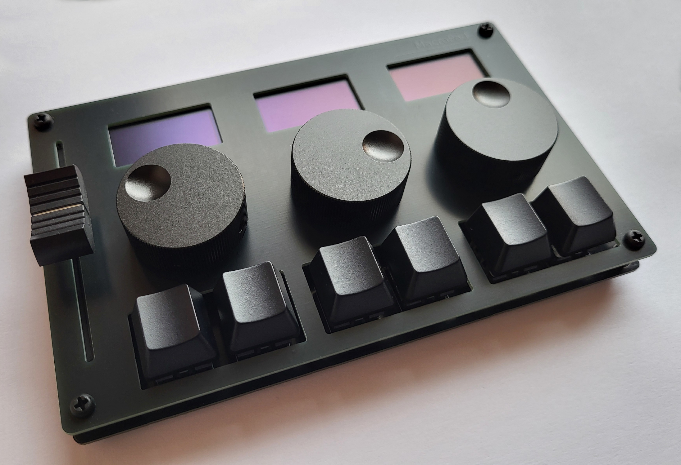
[!NOTE] This project is still under development. While almost everything works on Linux, Windows is a mess.
MacroPad is a USB input device with six keys, three rotary encoders, a slider, and three OLED displays. All controls can be configured to send user-defined mouse or keyboard input to the computer. Multiple profiles are supported, allowing you to change between different key-assignments with the press of a button. Typical applications include audio and video editing, computer graphics, and presentations.
MacroPad implements standard USB HID (human interface) device classes and thus requires no driver. The only is software that is needed is a Program for Configuring it and potentially some software for the slider.
MacroPad is powered by a Raspberry Pi Pico using the RP2040 microcontroller.
When plugged into a computer, MacroPad presents itself as a three-in-one input device composed of a keyboard, a mouse, and a miscellaneous input device. All keys and rotary encoders can be configured to send keyboard or mouse input to the computer.
The slider is also an HID-class device that needs no driver. However, most operating systems don't know what to do with slider input and so they just ignore it. For that reason, you will most likely want to have a piece of software running that consumes these inputs and performs certain actions, like adjusting volume or changing the brush size in a drawing application. You can find several examples in the SliderApps folder.
MacroPad is not sold anywhere. In this repository, you can find all the necessary information and code to build a MacroPad yourself. Please have a look at the Building Instructions and the User's Guide. Building a MacroPad is not particularly difficult. As long as you can hold a soldering iron without touching the wrong end, you should be fine.
| Qty | Value | Footprint | References |
|---|---|---|---|
| 6 | SW_Push | Button_Switch_Keyboard:SW_Cherry_MX_1.00u_PCB | SW1, SW2, SW3, SW4, SW5, SW6 |
| 3 | RotaryEncoder_Switch | Rotary_Encoder:RotaryEncoder_Alps_EC11E-Switch_Vertical_H20mm | SW7, SW8, SW9 |
| 3 | ~ | MacroPad:OLED 1.3in | DS1, DS2, DS3 |
| 2 | 4k7 | Resistor_SMD:R_1206_3216Metric_Pad1.30x1.75mm_HandSolder | R1, R2 |
| 1 | 100nF | Capacitor_SMD:C_1206_3216Metric_Pad1.33x1.80mm_HandSolder | C2 |
| 1 | 24CXX | Package_SO:SOIC-8_3.9x4.9mm_P1.27mm | U2 |
| 1 | BOOTSEL | MacroPad:MicroSwitch | SW10 |
| 1 | C | Capacitor_SMD:C_1206_3216Metric_Pad1.33x1.80mm_HandSolder | C1 |
| 1 | CONN_I2C | Connector_PinHeader_2.54mm:PinHeader_1x04_P2.54mm_Horizontal | J4 |
| 1 | JP_A0 | Jumper:SolderJumper-2_P1.3mm_Bridged_RoundedPad1.0x1.5mm | JP1 |
| 1 | JP_A1 | Jumper:SolderJumper-2_P1.3mm_Bridged_RoundedPad1.0x1.5mm | JP2 |
| 1 | JP_A2 | Jumper:SolderJumper-2_P1.3mm_Bridged_RoundedPad1.0x1.5mm | JP3 |
| 1 | LM4040DBZ-3 | Package_TO_SOT_SMD:SOT-23 | U3 |
| 1 | RESET | MacroPad:MicroSwitch | SW11 |
| 1 | R_Potentiometer_Dual | MacroPad:ALPS_RS60112 | RV1 |
| 1 | SWD | Connector_PinHeader_2.54mm:PinHeader_1x03_P2.54mm_Horizontal | J1 |
| 1 | SWD | Connector_JST:JST_SH_SM03B-SRSS-TB_1x03-1MP_P1.00mm_Horizontal | J2 |
| 1 | UART | Connector_PinHeader_2.54mm:PinHeader_1x02_P2.54mm_Horizontal | J3 |
| 1 | ~ | MacroPad:RPi_Pico_SMD_TH | U1 |
It measures 160 × 99.1 mm and has 2 copper layers, 1.6 mm thick.
29 parts. The full list of its parts is on this page, with links to each part's symbol and footprint where PCBKit's library has them.
From the 7vgn/MacroPad repository on GitHub, at the commit this page was made from: the board is PCB/MacroPad.kicad_pcb and its schematic PCB/MacroPad.kicad_sch. PCBKit opens the board in the browser, with nothing to install.
Its repository states no licence, so its author keeps all rights: ask 7vgn before reusing the design.
gusmanb/logicanalyzer
24 channel, 100Msps logic analyzer hardware and software

VoronDesign/Voron-Hardware
Cool Hardware designed by the Voron Design group

hoglet67/RGBtoHDMI
Bare-metal Raspberry Pi project that provides pixel-perfect sampling of Retro Computer RGB/YUV video and conversion to HDMI

hackclub/OnBoard
💡 Join 1,000 teenagers and make your first PCB with a $100 grant!

OLIMEX/DIY-LAPTOP
Do It Yourself Open Source Hardware and Software Modular Hacker's Friendly Laptop

UtilitechAS/amsreader-firmware
ESP8266 and ESP32 compatible firmware to read, interpret and publish data to MQTT from smart electrical meters, both DLMS and DSMR is supported

