2 layers426 × 307 mm
I7000
felipesanches/Itautec_I7000_KICAD
Esquemáticos do computador Itautec I-7000 G desenhados a partir de inspeção do circuito das PCBs
115 parts

 7FFD/ZX-SDC
Hardware version of z-controller (SD Card)
ZX SDC is an open-source printed circuit board by 7FFD, from the 7FFD/ZX-SDC repository on GitHub, published under the GPL-3.0 licence. It is a 2-layer board of 80 × 125.7 mm with 67 parts on 113 nets, routed with 983 tracks and 146 vias.
It is built around the 74LS125DC, 74LS74PC and 74LS04PC, with the 74LS163APC, 74LS166AP-E and 74LS30PC among its other parts. Its parts include 23 resistors, 11 capacitors, 11 ICs, 11 diodes and 3 connectors.


Hardware version of z-controller (SD Card)
My motivation on creation this design was to avoid usage of CPLD and show that it's possible to design such controller with ICs.
This controller is intended to connect your ZX Spectrum / Clone with SD Card. That gives ability to copy files between SD Card with FAT16/32 to TRDOS (Beta Drive Interface), Nemo IDE and etc.
As an example, you can use FATALL file manager that runs from TRD.
This controller is almost fully compatible with original z-controller. There are couple of differences:
Control Port: 0x77
Data Port: 0x57
Because current board design was done for ZXBUS, if you want to connect to your ZX Spectrum clone then you will need to solder adapter based on documentation for your computer. Carefully check all signals, they are all important! As an example: /WAIT.
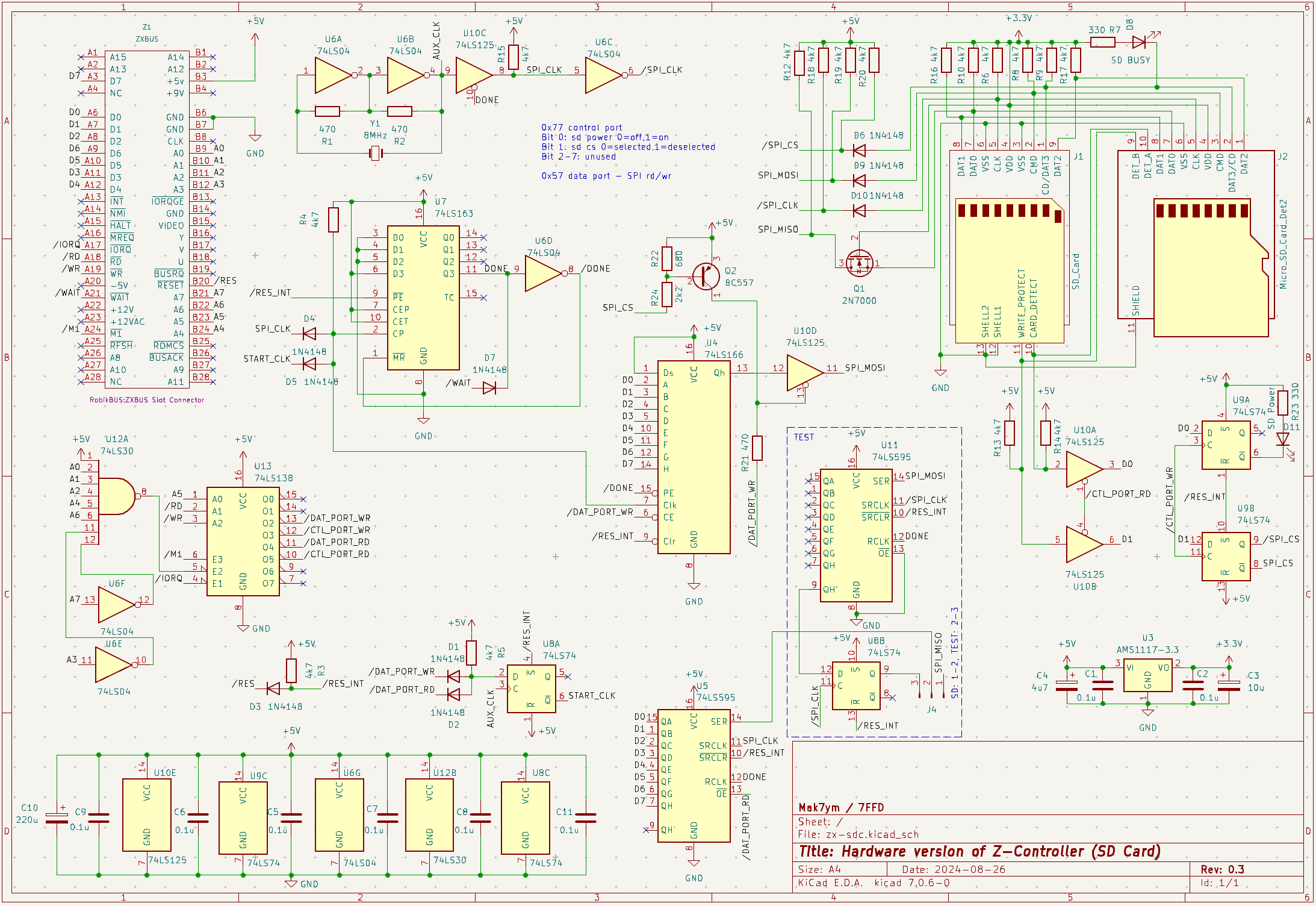
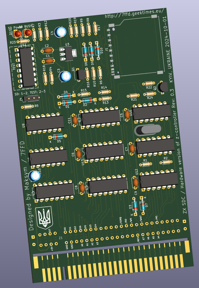
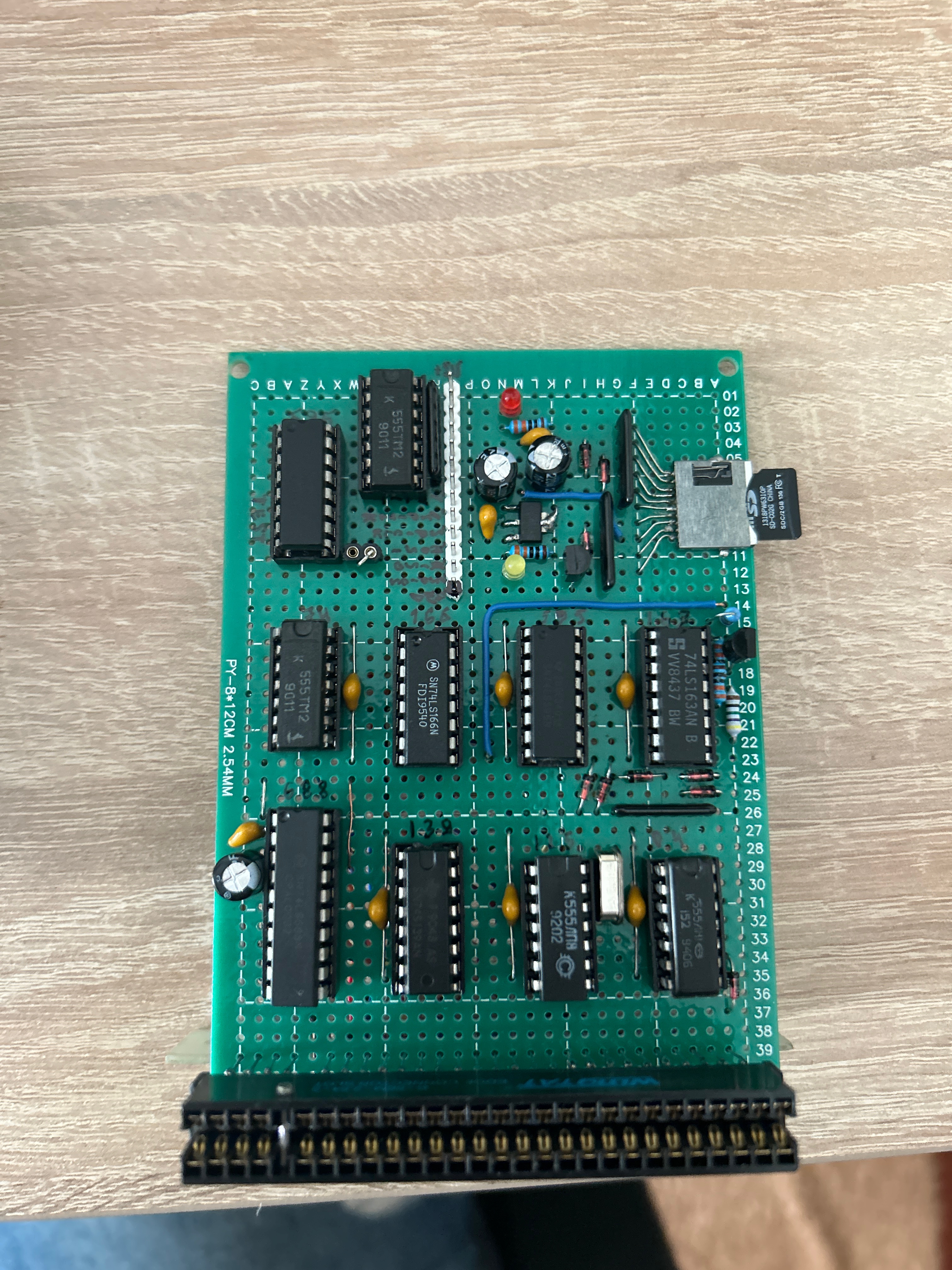
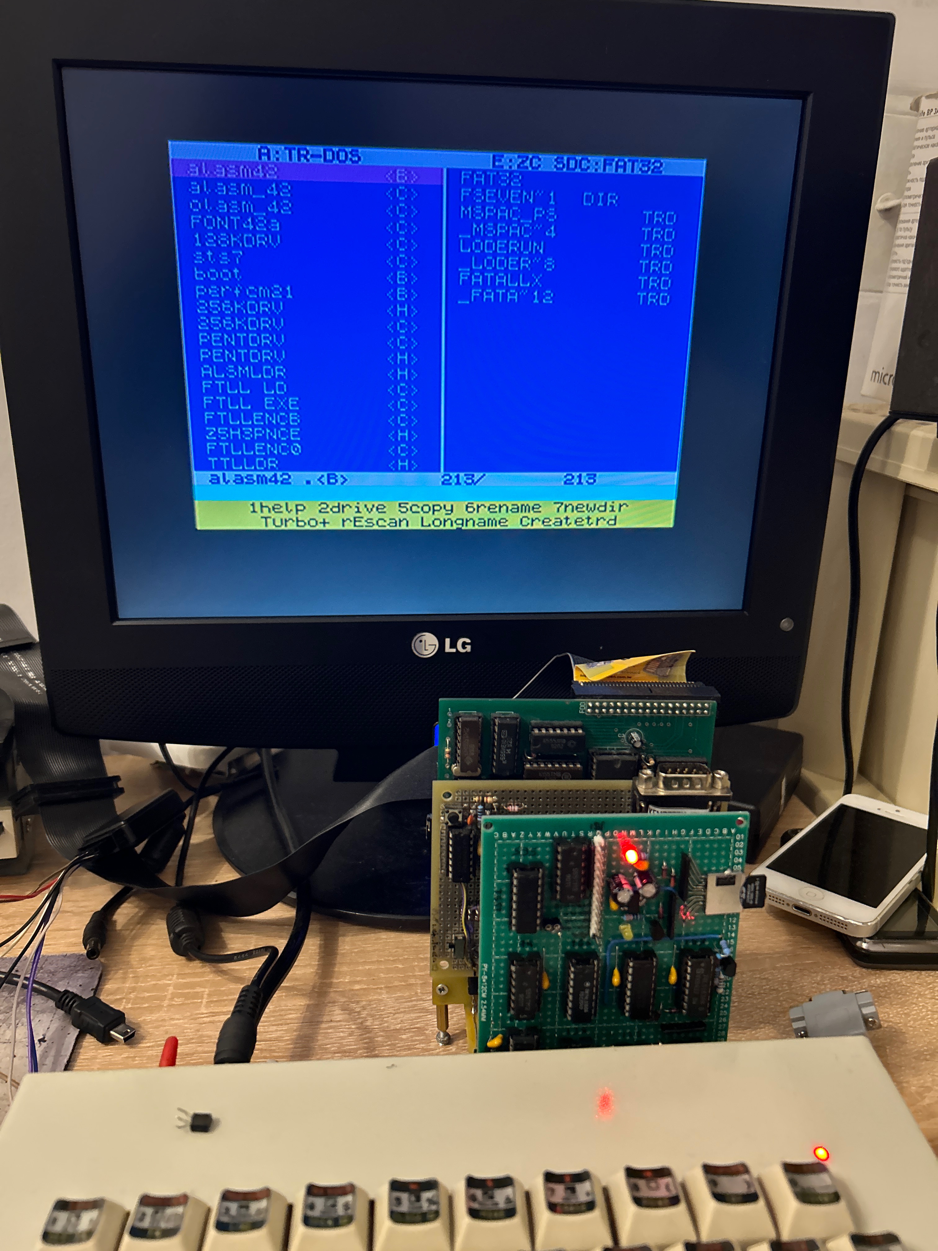
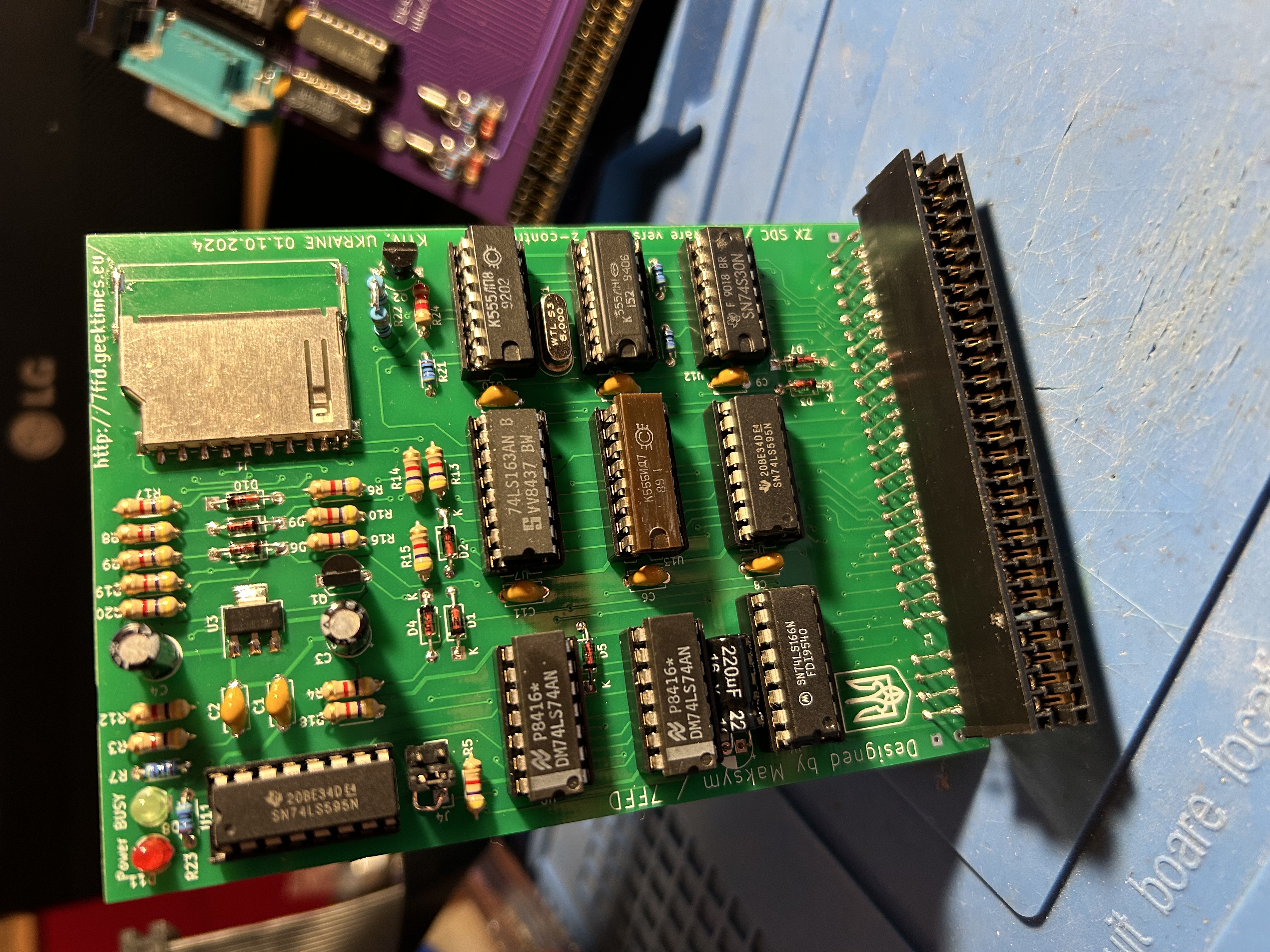
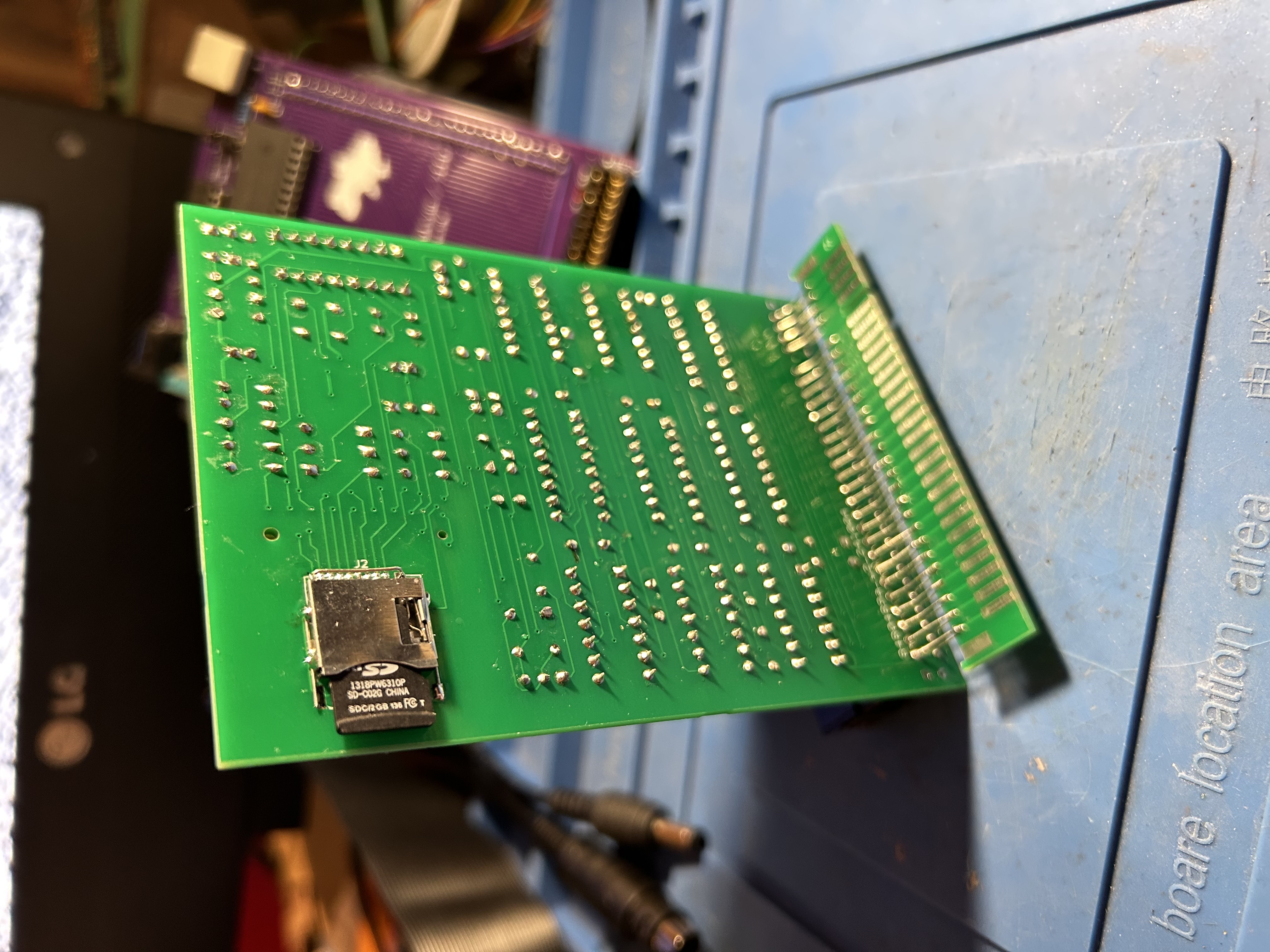
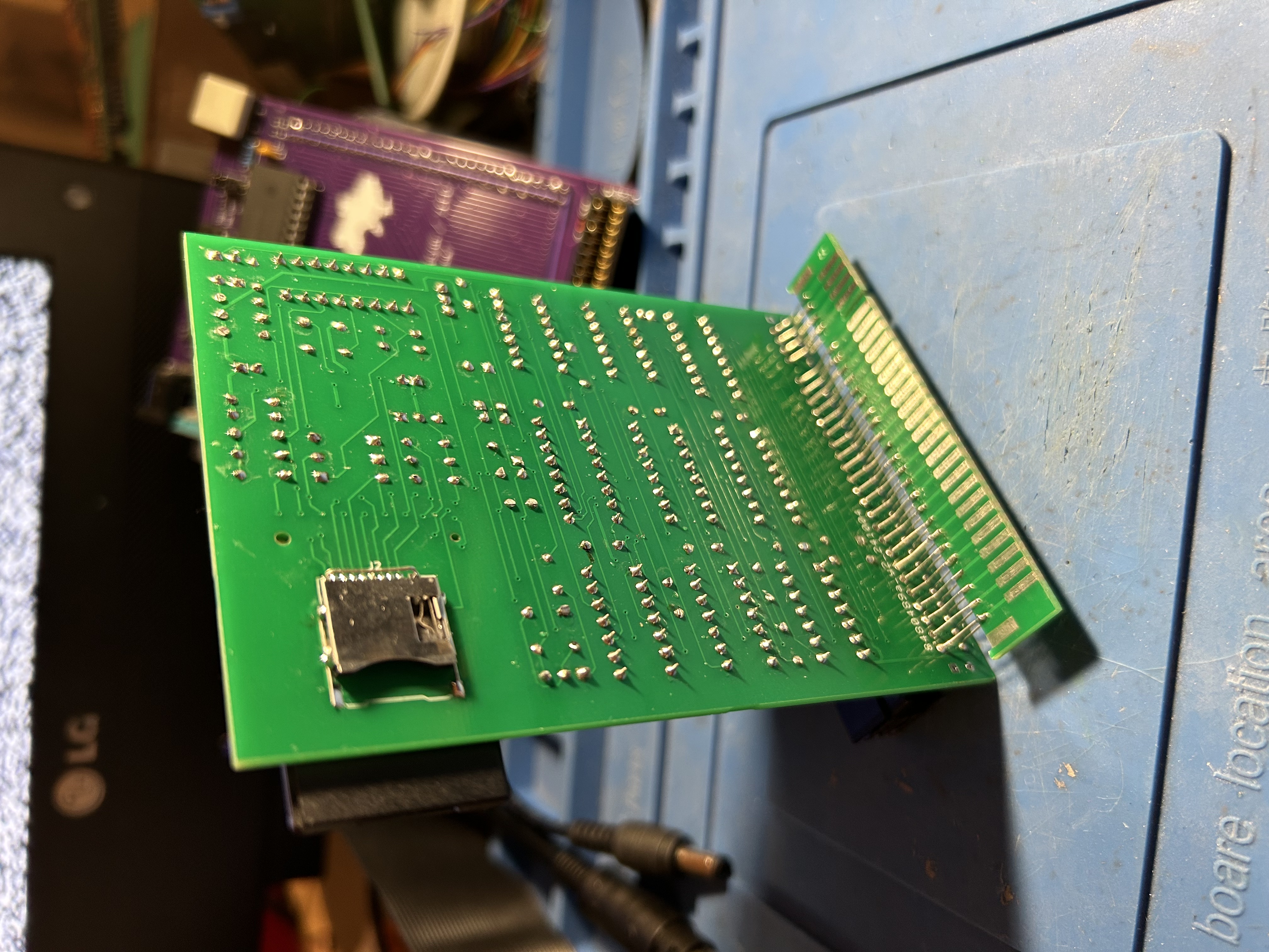
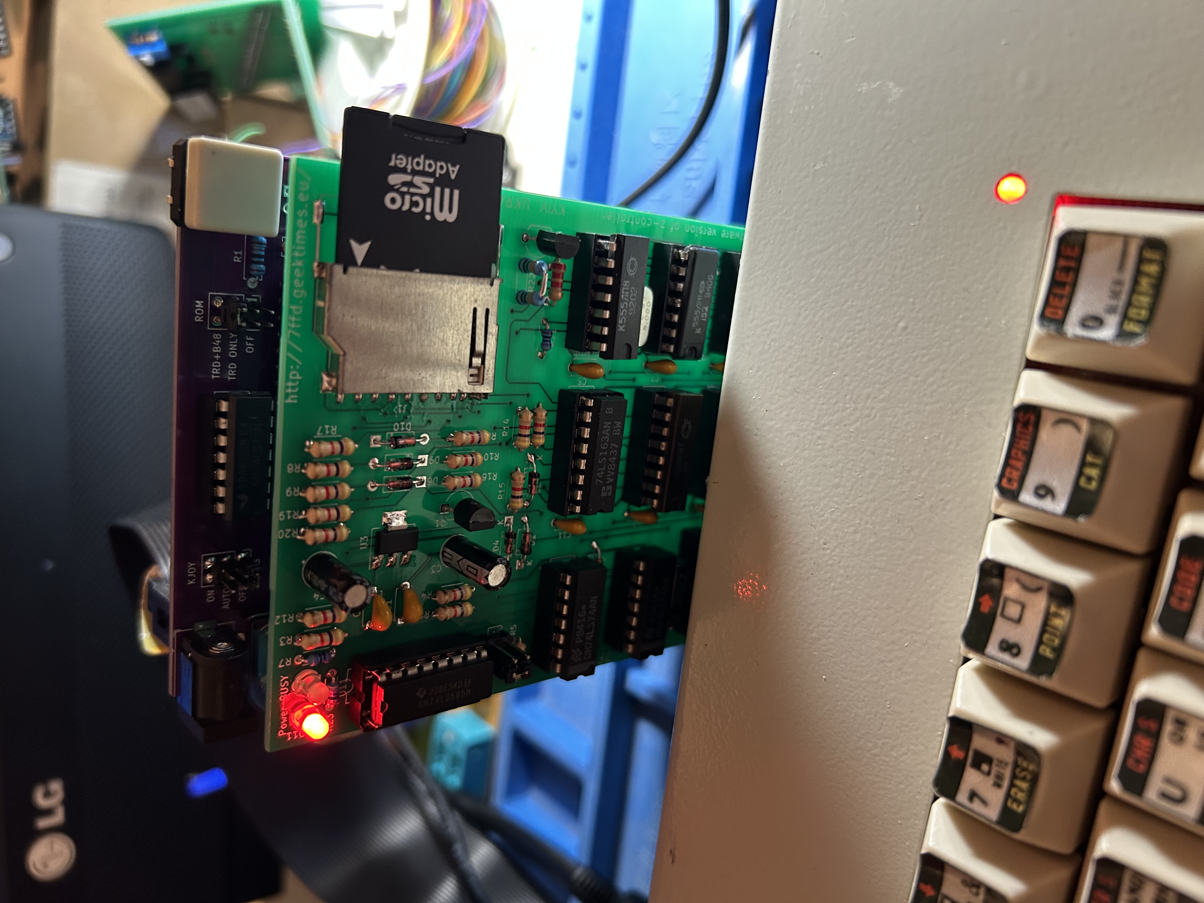
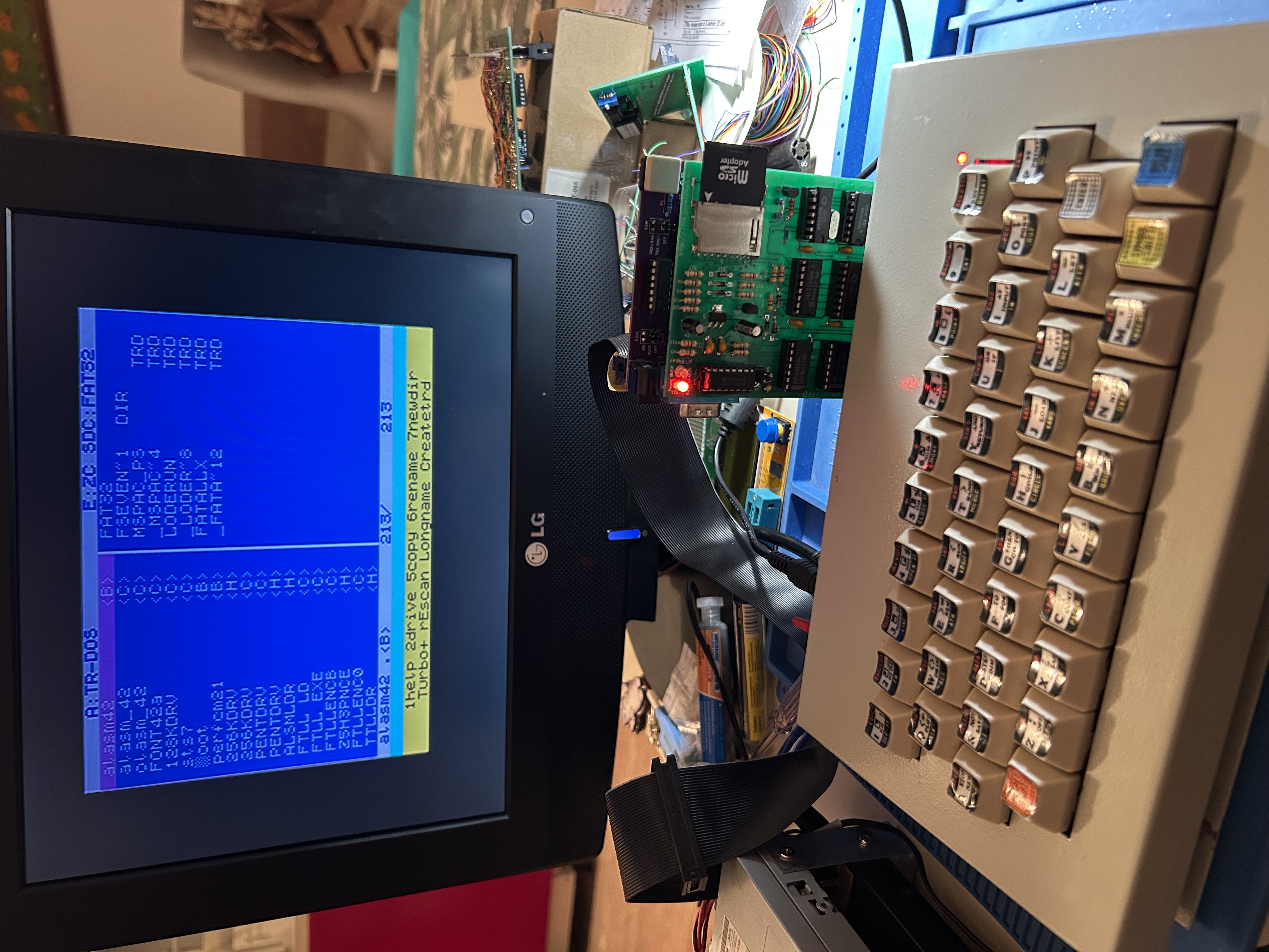
U11 and J4 has been added to the board for debugging purpose. Since board has been tested and doesn't need to be tuned if assembled correct, you can skip soldering U11 or use socket for it. J4: 1-2 SD Card, 2-3 U11 Test IC connection
In case you decided to make sure that board assembled right and works correct, follow this checklist:
NOTE: SD Card must be formatted in FAT32/16!!!
| Qty | Value | Footprint | References |
|---|---|---|---|
| 16 | 4k7 | Resistor_THT:R_Axial_DIN0204_L3.6mm_D1.6mm_P5.08mm_Horizontal | R3, R4, R5, R6, R8, R9, R10, R12, R13, R14, R15, R16, R17, R18, R19, R20 |
| 9 | 1N4148 | Diode_THT:D_DO-35_SOD27_P7.62mm_Horizontal | D1, D2, D3, D4, D5, D6, D7, D9, D10 |
| 8 | 0.1u | Capacitor_THT:C_Disc_D4.7mm_W2.5mm_P5.00mm | C1, C2, C5, C6, C7, C8, C9, C11 |
| 3 | 470 | Resistor_THT:R_Axial_DIN0204_L3.6mm_D1.6mm_P5.08mm_Horizontal | R1, R2, R21 |
| 2 | 330 | Resistor_THT:R_Axial_DIN0204_L3.6mm_D1.6mm_P5.08mm_Horizontal | R7, R23 |
| 2 | 74LS595 | Package_DIP:DIP-16_W7.62mm | U5, U11 |
| 2 | 74LS74 | Package_DIP:DIP-14_W7.62mm | U8, U9 |
| 1 | 10u | Capacitor_THT:CP_Radial_D5.0mm_P2.00mm | C3 |
| 1 | 220u | Capacitor_THT:CP_Radial_D5.0mm_P2.00mm | C10 |
| 1 | 2N7000 | Package_TO_SOT_THT:TO-92_Inline_Wide | Q1 |
| 1 | 2k2 | Resistor_THT:R_Axial_DIN0204_L3.6mm_D1.6mm_P5.08mm_Horizontal | R24 |
| 1 | 4u7 | Capacitor_THT:CP_Radial_D5.0mm_P2.00mm | C4 |
| 1 | 680 | Resistor_THT:R_Axial_DIN0204_L3.6mm_D1.6mm_P5.08mm_Horizontal | R22 |
| 1 | 74LS04 | Package_DIP:DIP-14_W7.62mm | U6 |
| 1 | 74LS125 | Package_DIP:DIP-14_W7.62mm | U10 |
| 1 | 74LS138 | Package_DIP:DIP-16_W7.62mm | U13 |
| 1 | 74LS163 | Package_DIP:DIP-16_W7.62mm | U7 |
| 1 | 74LS166 | Package_DIP:DIP-16_W7.62mm | U4 |
| 1 | 74LS30 | Package_DIP:DIP-14_W7.62mm | U12 |
| 1 | 8MHz | Crystal:Crystal_HC18-U_Vertical | Y1 |
| 1 | AMS1117-3.3 | Package_TO_SOT_SMD:SOT-223-3_TabPin2 | U3 |
| 1 | BC557 | Package_TO_SOT_THT:TO-92_Inline_Wide | Q2 |
| 1 | Conn_01x03_Pin | Connector_PinHeader_2.54mm:PinHeader_1x03_P2.54mm_Vertical | J4 |
| 1 | Micro_SD_Card_Det2 | Connector_Card:microSD_HC_Hirose_DM3AT-SF-PEJM5 | J2 |
| 1 | SD BUSY | LED_THT:LED_D3.0mm | D8 |
| 1 | SD Power | LED_THT:LED_D3.0mm | D11 |
| 1 | SD_Card | Connector_Card:SD_TE_2041021 | J1 |
| 1 | UA CoA 8x11mm | Symbol:UA CoA 8x11mm | UA CoA |
| 1 | ZXBUS | RobikBUS:ZXBUS Slot Connector | Z1 |
| 1 | ZXBUS | RobikBUS:ZXBUS | Z2 |
The 65 most common of 67 parts.
It measures 80 × 125.7 mm and has 2 copper layers, 1.6 mm thick.
67 parts, built around the 74LS125DC, 74LS74PC, 74LS04PC and 74LS163APC. The full list of its parts is on this page, with links to each part's symbol and footprint where PCBKit's library has them.
From the 7FFD/ZX-SDC repository on GitHub, at the commit this page was made from: the board is zx-sdc.kicad_pcb and its schematic alt-port-decoder.kicad_sch. PCBKit opens the board in the browser, with nothing to install.
Its repository publishes it under the GPL-3.0 licence: you may reuse it on that licence's terms (keep the author's notice, and for a copyleft licence share your changes alike).
felipesanches/Itautec_I7000_KICAD
Esquemáticos do computador Itautec I-7000 G desenhados a partir de inspeção do circuito das PCBs

ksr/YACC1-D
YACC1 (Yet Another Custom CPU) - definitive tree: hardware, firmware, software, tools and docs for the hand-built TTL computer. Supersedes ksr/YACC1-2020.

Bambelweeny57/OSI-600D-SuperBoard-II
KiCad 10 recreation of the Ohio Scientific Superboard II Model 600 rev D (1980) with Cherry MX keyswitches, 27C16/2816 ROMs, full schematic and assembly guide.

hkzlab/CGA_Redux
The Color Graphics Adapter Redux board is a more or less faithful clone of the original IBM CGA, based on the original schematics

kev-ju/PC-Retro-MTM
Modern KiCad version of the IBM 5150 system board originally created by MTM Scientific, Inc.

ibaldachini/C64NIKI2
This work is licensed under a [Creative Commons Attribution-NonCommercial-ShareAlike 4.0 International License][cc-by-nc-sa].

jimbro1000/DIY-Video
General purpose video system for 8-bit computers using 74LS logic
