2 layers100 × 100 mm
Smartmeter IR multi
greenMikeEU/shrdzm
SHRDZM (just a name, not an acronym) is an ESP8285/ESP8266 based sensor and actor integration platform.
340 partsGPL-3.0

 3DES/WatchdogBoard
watchdog PCB with one watchdog output, up to seven ordinary outputs and four inputs
USBIOModule is an open-source printed circuit board by 3DES, from the 3DES/WatchdogBoard repository on GitHub. It is a 2-layer board of 98.4 × 54.4 mm with 98 parts on 102 nets, routed with 630 tracks and 32 vias.
It is built around the LTV-847S, BC817 and BAT46, with the BSS138 among its other parts. Its parts include 31 diodes, 17 resistors, 16 transistors, 12 capacitors and 8 connectors. It belongs with the AVR (ATmega, ATtiny) boards of this library.


Watchdog PCB, has 8 outputs and 4 inputs. The first output is used as watchdog output and will be switched off if not triggered regularely. Input 0 is the watchdog readback to check if the watchdog can still switch off the output 0 relay.
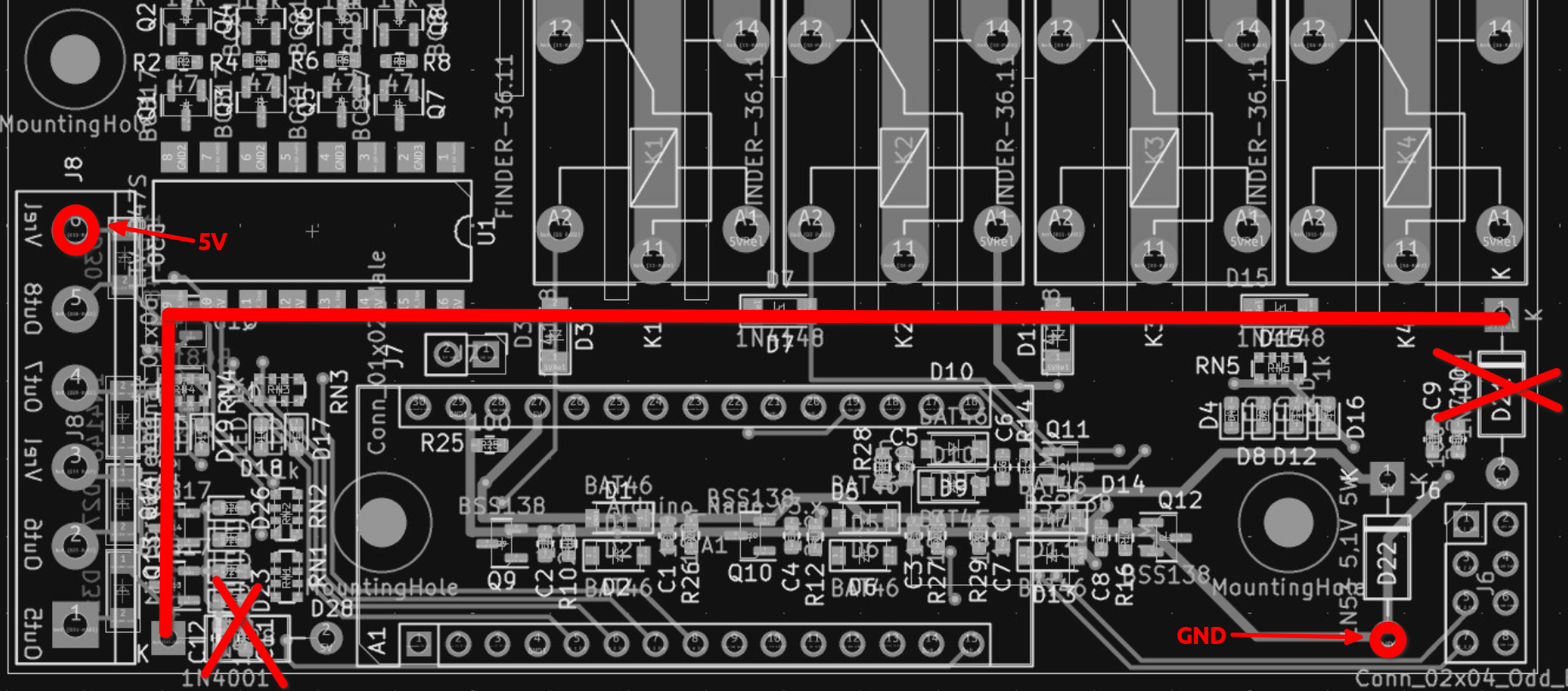
The relays are powered via USB 5V, what, depending on the used USB cable, can be a bit less sometimes. If you have problems with that change the USB cable or change the layout:
| Qty | Value | Footprint | References |
|---|---|---|---|
| 12 | BC817 | Package_TO_SOT_SMD:SOT-23 | Q1, Q2, Q3, Q4, Q5, Q6, Q7, Q8, Q13, Q14, Q15, Q16 |
| 12 | LED | LED_SMD:LED_0603_1608Metric | D4, D8, D12, D16, D17, D18, D19, D20, D23, D24, D25, D26 |
| 8 | 1N4148 | Diode_SMD:D_MiniMELF | D3, D7, D11, D15, D27, D29, D30, D31 |
| 8 | BAT46 | Diode_SMD:D_SOD-123 | D1, D2, D5, D6, D9, D10, D13, D14 |
| 6 | 100n | Capacitor_SMD:C_0603_1608Metric | C1, C3, C5, C7, C10, C12 |
| 6 | 2u2 | Capacitor_SMD:C_0603_1608Metric | C2, C4, C6, C8, C9, C11 |
| 5 | 100 | Resistor_SMD:R_0603_1608Metric | R25, R26, R27, R28, R29 |
| 5 | 1k | Resistor_SMD:R_Array_Convex_4x0612 | RN1, RN2, RN3, RN4, RN5 |
| 4 | 10k | Resistor_SMD:R_0603_1608Metric | R1, R3, R5, R7 |
| 4 | 1M | Resistor_SMD:R_0603_1608Metric | R10, R12, R14, R16 |
| 4 | 47 | Resistor_SMD:R_0603_1608Metric | R2, R4, R6, R8 |
| 4 | BSS138 | Package_TO_SOT_SMD:SOT-23 | Q9, Q10, Q11, Q12 |
| 4 | FINDER-36.11 | Relay_THT:Relay_SPDT_Finder_36.11 | K1, K2, K3, K4 |
| 4 | Screw_Terminal_01x03 | TerminalBlock:TerminalBlock_bornier-3_P5.08mm | J1, J2, J3, J4 |
| 3 | MountingHole | MountingHole:MountingHole_3.2mm_M3 | H1, H2, H3 |
| 2 | 1N4001 | Diode_THT:D_DO-41_SOD81_P10.16mm_Horizontal | D21, D28 |
| 2 | Screw_Terminal_01x06 | TerminalBlock:TerminalBlock_bornier-6_P5.08mm | J5, J8 |
| 1 | 1N53 5,1V 5W | Diode_THT:D_DO-41_SOD81_P10.16mm_Horizontal | D22 |
| 1 | Arduino_Nano_v3.x | Module:Arduino_Nano | A1 |
| 1 | Conn_01x02_Male | Connector_PinHeader_2.54mm:PinHeader_1x02_P2.54mm_Vertical | J7 |
| 1 | Conn_02x04_Odd_Even | Connector_PinHeader_2.54mm:PinHeader_2x04_P2.54mm_Vertical | J6 |
| 1 | LTV-847S | Package_DIP:SMDIP-16_W9.53mm | U1 |
It measures 98.4 × 54.4 mm and has 2 copper layers, 1.6 mm thick.
98 parts, built around the LTV-847S, BC817, BAT46 and BSS138. The full list of its parts is on this page, with links to each part's symbol and footprint where PCBKit's library has them.
From the 3DES/WatchdogBoard repository on GitHub, at the commit this page was made from: the board is WatchdogBoard/PcbProductionData/project/USBIOModule.kicad_pcb and its schematic WatchdogBoard/PcbProductionData/project/USBIOModule.kicad_sch. PCBKit opens the board in the browser, with nothing to install.
Its repository states no licence, so its author keeps all rights: ask 3DES before reusing the design.
greenMikeEU/shrdzm
SHRDZM (just a name, not an acronym) is an ESP8285/ESP8266 based sensor and actor integration platform.

ieb/N2KEngineEsp32
N2K Engine Interface with BLE built around an ESP32 and ADS1115 ADCs

bryce-builds/PiGarage
Open-source Raspberry Pi power management and audio HAT for automotive head-unit use


Elektropac/MCS_Control
All the firmware for Control module

