Skip to the content
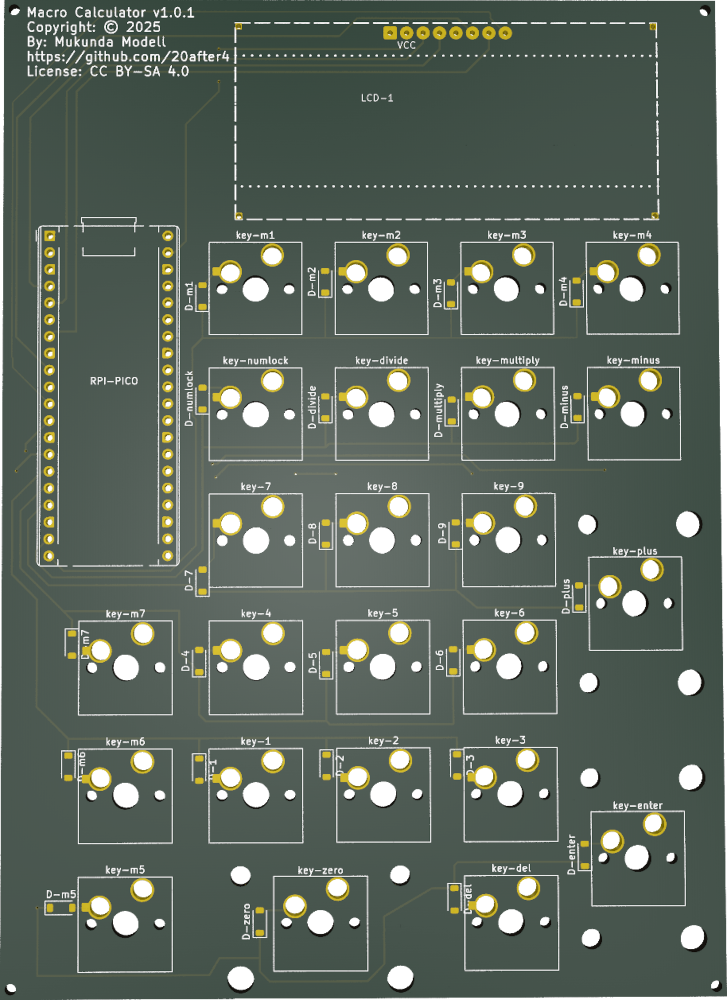
2 layers108 × 150 mmNumpad, the printed circuit board in 3D

Custom USB Keyboard & Standalone Calculator written in MicroPython for the RP2350

Size
108 × 150 mm
Copper layers
2
Thickness
1.6 mm
Parts
54
Nets
43
Pads
299
Tracks, vias
310, 11
Pours
24
Routed
Yes
KiCad
KiCad 9.0 (file 20241229)
Created
9 Oct 2025
Updated
22 Oct 2025

Overview

Numpad is an open-source printed circuit board by 20after4, from the 20after4/macro-calculator repository on GitHub. It is a 2-layer board of 108 × 150 mm with 54 parts on 43 nets, routed with 310 tracks and 11 vias.

It belongs with the keyboards and input boards and the RP2040 boards of this library.

README

README.md

MacroCalculator

Custom Mechanical USB Keypad + Standalone Calculator written in MicroPython

Hardware:

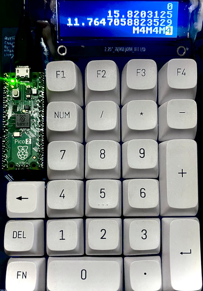
Illustration of the circuit board Photo of the prototype

  • Custom 24 Key Matrix PCB
    • Supports hot-swapable MX-style key switches
    • Hand solderable (Difficulty: medium-high due to small surface mount diodes)
    • Standard PC Numpad Keys
    • 7 extra macro keys
    • Sockets for MCU and LCD via pin headers.
  • RPi Pico 2 (RP2350 MCU)
  • 72x284 resolution ST7789 LCD Screen: 16px font = 4 lines x 17 characters

Software / Firmware

Custom Python App running on lvgl/lv_micropython firmware.

The NumLock key toggles between two modes:

  • Calc mode:
    • Basic calculator functionality
    • 17 digits of decimal precision
    • Basic expression evaluation
    • Named variables assignable to the macro keys
    • Scrollable history buffer
  • Keypad mode:
    • Basic USB HID Numpad
    • Macro keys programmable with MicroPython for nearly unlimited flexibility.

Acknoledgements

Here I credit the projects that made this one possible. This project draws on these other open source projects for inspiration and some of the components used in developing macro-calc:

  • Raspberry Pi Pico - The RP2040 and successors have proven to be a very affordable and accessible microcontroller development platform which has significantly lowered the barrier to entry for embedded development.
  • MicroPython: The programming language runtime and embedded firmware infrastructure.
  • LVGL - Graphics API for embedded devices which I've utilized in order to support the LCD display in this project.
  • lvgl/lv_micropython is a fork of micropython designed for building microcontroller Firmware with integrated LVGL graphics capabilities compiled into the micropython runtime. This is the foundation I've used to build the firmware for this project.
  • lvgl_micropython deserves an honorable mention. This is an alternative fork, based on the previously mentioned project. Although I don't currently use this fork to build my firmware, I have learned quite a lot about TFT Display chips from studying their source code, issues and discussions on github and on the lvgl forums.
  • mpy-dev/micropython-decimal-number provides a basis for sane decimal arithmatic. This has proven very helpful for the calculator portion of this project. Floating point math isn't a good fit for a general purpose calculator.

Parts

54
QtyValueFootprintReferences
24D_SOD-123Diode_SMD:D_SOD-123D-1, D-2, D-3, D-4, D-5, D-6, D-7, D-8, D-9, D-del, D-divide, D-enter, D-m1, D-m2, D-m3, D-m4 +8
21SW_Cherry_MX_1.00u_PCB_HOTSWAPmy footprints:SW_Cherry_MX_1.00u_PCB_HOTSWAPkey-1, key-2, key-3, key-4, key-5, key-6, key-7, key-8, key-9, key-del, key-divide, key-m1, key-m2, key-m3, key-m4, key-m5 +5
4, , ,
2SW_Cherry_MX_2.00u_Vertical_PCBButton_Switch_Keyboard:SW_Cherry_MX_2.00u_Vertical_PCBkey-enter, key-plus
12.25in LCDmy footprints:2.25in LCD DISPLAY 284x76LCD-1
1RaspberryPi_Pico_Common_THTModule:RaspberryPi_Pico_Common_THTRPI-PICO
1SW_Cherry_MX_2.00u_PCBButton_Switch_Keyboard:SW_Cherry_MX_2.00u_PCBkey-zero

Similar boards

  • 2 layers203 × 26.6 mmBlade13, the printed circuit board in 3D

    Blade13

    opulo-inc/lumenpnp

    The LumenPnP is an open source pick and place machine.

    54 parts3.7k
  • 2 layers30 × 50 mmModuleV421, the printed circuit board in 3D

    ModuleV421

    stuartpittaway/diyBMSv4

    Version 4 of the diyBMS

    54 parts1.1k
  • 2 layers100.1 × 40 mm32Bit shift register, the printed circuit board in 3D

    32Bit shift register

    MaltWhiskey/Mega-Cube

    16x16x16 PL9823 Cube with Teensy 4.0 and FlexIO driver

    54 parts766
  • 2 layers100 × 120 mmHubble lens, the printed circuit board in 3D

    Hubble lens

    wntrblm/Castor_and_Pollux

    A Juno-inspired dual oscillator

    54 parts587
  • 2 layersPassword, the printed circuit board in 3D

    Password

    limpkin/mooltipass

    Github repository dedicated to the mooltipass project

    54 parts531
  • 2 layers104.3 × 38.9 mmHYD ISO PANEL, the printed circuit board in 3D

    HYD ISO PANEL

    jrsteensen/OpenHornet

    OpenHornet 1:1 F/A-18C Simulator Repository

    54 parts431
  • 2 layers93.8 × 64.2 mmPiFinder smt, the printed circuit board in 3D

    PiFinder smt

    brickbots/PiFinder

    A plate solving telescope finder based around a Raspberry PI and RPI HQ Camera

    54 parts257GPL-3.0

Questions

How big is the Numpad PCB?

It measures 108 × 150 mm and has 2 copper layers, 1.6 mm thick.

What parts does the Numpad use?

54 parts. The full list of its parts is on this page, with links to each part's symbol and footprint where PCBKit's library has them.

Where can I download the Numpad KiCad files?

From the 20after4/macro-calculator repository on GitHub, at the commit this page was made from: the board is hardware/numpad/numpad.kicad_pcb and its schematic hardware/numpad/numpad.kicad_sch. PCBKit opens the board in the browser, with nothing to install.

Can I use the Numpad design in my own project?

Its repository states no licence, so its author keeps all rights: ask 20after4 before reusing the design.