Skip to the content
PCBKitNew board
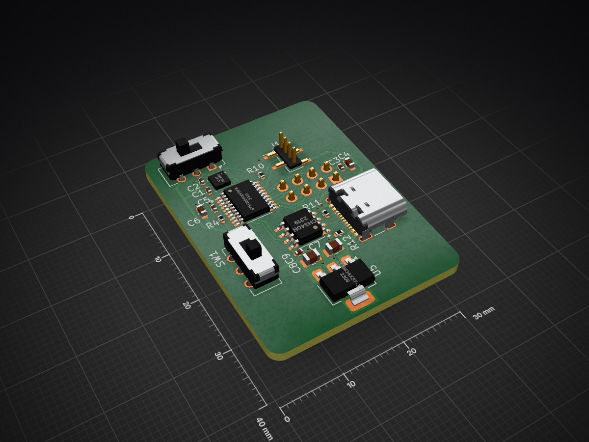
2 layers30 × 40 mmTemp Reader, the printed circuit board in 3D

This directory contains the hardware design files for the Temp Reader (Transmitter Node) project, developed using KiCad.

Size
30 × 40 mm
Copper layers
2
Thickness
1.6 mm
Parts
22
Nets
35
Pads
112
Tracks, vias
151, 21
Pours
5
Routed
Yes
KiCad
KiCad 10.0 (file 20260206)
Created
23 Jun 2026
Updated
24 Aug 2026

Overview

Temp Reader is an open-source printed circuit board by 12Robert20, from the 12Robert20/Temp_Reader repository on GitHub. It is a 2-layer board of 30 × 40 mm with 22 parts on 35 nets, routed with 151 tracks and 21 vias.

It is built around the BME280 and CH340N. Its parts include 9 capacitors, 5 ICs, 4 resistors, 2 connectors and 2 switches. It belongs with the STM32 boards of this library.

Main components

2

README

Hardware/README.md

Hardware

This directory contains the hardware design files for the Temp Reader (Transmitter Node) project, developed using KiCad.

Contents

  • Temp Reader.kicad_pro – KiCad project file
  • Temp Reader.kicad_sch – Schematic (single-sheet flattened design)
  • Temp Reader.kicad_pcb – PCB layout

Hardware Overview

This specific board functions as the Transmitter Node for environmental telemetry. The hardware architecture has been transitioned to an STM32-based core. The custom PCB is a fully routed 2-layer design featuring dedicated copper pours for GND, +3.3V, and VBUS to ensure robust power distribution and signal integrity.

Component Stack:

  • STM32G030F6Px MCU (Main microcontroller, chosen for low-power and efficient embedded processing)
  • Bosch BME280 (Environmental sensor for highly accurate temperature, humidity, and pressure readings)
  • nRF24L01 Wireless Transceiver (External breakout module variant for extended range off-grid communication)
  • LT1963AxST-3.3 LDO Regulator (Low-noise 3.3V linear regulator ensuring stable power delivery for the MCU and RF module)
  • CH340N USB-to-Serial Bridge (Integrated UART communication via a modern USB-C receptacle)
  • Programming Header (J1) (4-pin interface exposing GND, BOOT, SWDIO, and +3.3V for straightforward firmware flashing)
  • Physical Controls (SW1, SW2) (SPDT slide switches for configuration/boot modes)

Current Status

  • ✅ Electronic schematics completed (Single-sheet architecture)
  • ✅ PCB layout completed (Fully routed 2-layer board)
  • ⏳ Firmware development planned
  • ⏳ Hardware testing pending

Software

The firmware is not included in this directory and will be available in the /Firmware folder once development begins. The STM32 transmitter firmware will utilize the STM32 hardware abstraction layer (HAL/LL) or a custom bare-metal approach.
Parts

22
QtyValueFootprintReferences
3100nFCapacitor_SMD:C_0402_1005MetricC1, C2, C3
210kResistor_SMD:R_0402_1005MetricR4, R10
222uCapacitor_SMD:C_0805_2012MetricC7, C8
25K1Resistor_SMD:R_0402_1005MetricR11, R12
2SW_SPDTButton_Switch_THT:SW_CK_JS202011CQN_DPDT_StraightSW1, SW2
10.1uCapacitor_SMD:C_0402_1005MetricC9
1100nCapacitor_SMD:C_0402_1005MetricC5
110uCapacitor_SMD:C_0603_1608MetricC6
110uFCapacitor_SMD:C_0603_1608MetricC4
1BME280Package_LGA:Bosch_LGA-8_2.5x2.5mm_P0.65mm_ClockwisePinNumberingU2
1CH340NPackage_SO:JEITA_SOIC-8_3.9x4.9mm_P1.27mmU7
1Conn_01x04_PinConnector_PinHeader_1.27mm:PinHeader_1x04_P1.27mm_Vertical_SMD_Pin1LeftJ1
1LT1963AxST-3.3Package_TO_SOT_SMD:SOT-223-3_TabPin2U5
1NRF24L01_BreakoutRF_Module:nRF24L01_BreakoutU4
1STM32G030F6PxPackage_SO:TSSOP-20_4.4x6.5mm_P0.65mmU1
1USB_C_Receptacle_USB2.0_14PConnector_USB:USB_C_Receptacle_GCT_USB4105-xx-A_16P_TopMnt_HorizontalJ2

Questions

How big is the Temp Reader PCB?

It measures 30 × 40 mm and has 2 copper layers, 1.6 mm thick.

What parts does the Temp Reader use?

22 parts, built around the BME280 and CH340N. The full list of its parts is on this page, with links to each part's symbol and footprint where PCBKit's library has them.

Where can I download the Temp Reader KiCad files?

From the 12Robert20/Temp_Reader repository on GitHub, at the commit this page was made from: the board is Hardware/Temp Reader.kicad_pcb and its schematic Hardware/Temp Reader.kicad_sch. PCBKit opens the board in the browser, with nothing to install.

Can I use the Temp Reader design in my own project?

Its repository states no licence, so its author keeps all rights: ask 12Robert20 before reusing the design.

Similar boards

  • 2 layers50.5 × 94.7 mmSwordOfSecretsUSBProd, the printed circuit board in 3D

    SwordOfSecretsUSBProd

    gili-yankovitch/SwordOfSecrets

    To solve the challenge you will need to discover a series of flags, hidden inside the sword. Each one will help you unlock the next step in the challenge, to finally reveal the ultimate secret the sword holds.

    16 parts47MIT
  • 2 layers76 × 72 mmPanel, the printed circuit board in 3D

    Panel

    NandXor96/USBWLEDC

    USB WLED Controller

    184 parts40
  • 2 layers96 × 26 mmHack clock, the printed circuit board in 3D

    Hack clock

    hack-apollo/hack_clock

    A matrix LED WiFi clock.

    28 parts23GPL-3.0
  • 4 layers115.5 × 96.2 mmClosed deck x4, the printed circuit board in 3D

    Closed deck x4

    OpenLogicEFI/Hardware

    Hardware is based off an open source project called Speeduino by Josh Stewart.

    245 parts19
  • 6 layers129.8 × 57.4 mmIIsiA7 Mini, the printed circuit board in 3D

    IIsiA7 Mini

    MelkhiorVintageComputing/IIsiFPGA

    Stuff to put a FPGA in a Macintosh IIsi

    219 parts18
  • 4 layers60 × 95 mmDevboard, the printed circuit board in 3D

    Devboard

    tjclement/ecsc23-badge

    This repo contains the hardware designs and firmware developed for the ECSC23 hardware challenge by Curious Supplies.

    147 parts10
  • 4 layers48 × 96 mmMain Control Board, the printed circuit board in 3D

    Main Control Board

    baoqi-zhong/Awesome-SMT-Machine

    A single head 🔥SMT Machine🔥 based on FOC stepper motors. Pure self-developed and fully open-sourced.

    188 parts9
  • 2 layers75.3 × 33.8 mm24-ch relay driver kicad, the printed circuit board in 3D

    24-ch relay driver kicad

    dilshan/24ch-usb-high-voltage-driver

    24-Channel USB high voltage driver.

    35 parts5MIT