2 layers40 × 40 mm
ProPico
SunnyYoshimitsu/Reconfigurable-Space-Compute-Cluster
Here will be the repository for an "extremely reconfigurable satellite" aimed toward at competing in NASA Minds and hopefully assist Artemis in its missions.
66 parts3

 0xmanidev/dev-board
this is a project made for hackclub blueprint event
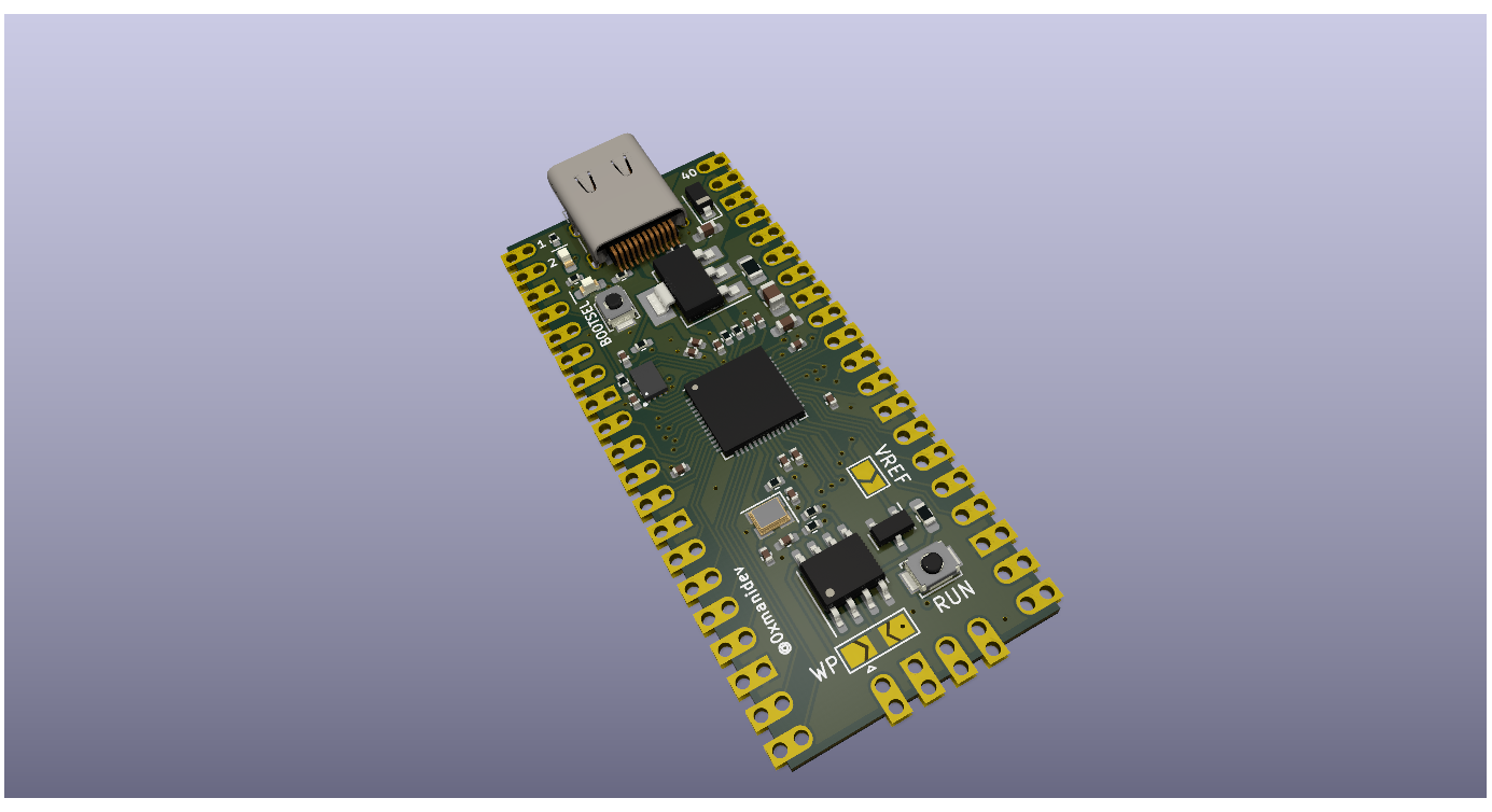
Dev board is an open-source printed circuit board by 0xmanidev, from the 0xmanidev/dev-board repository on GitHub, published under the MIT licence. It is a 2-layer board of 21 × 51 mm with 55 parts on 65 nets, routed with 464 tracks and 68 vias.
It is built around the RP2040, W25Q16JVUXIQ and AMS1117-3.3, with the FM24CL16B-G, B5819W and ECS-120-12-36-AGN-TR3 among its other parts. Its parts include 18 capacitors, 13 resistors, 5 ICs, 4 connectors and 3 diodes. It belongs with the microcontroller boards boards and the RP2040 boards of this library.


this is a project made for hackclub blueprint event I made this project to get more into pcb design and electronics this is a stepping stone for me because I always been a software kind of guy
I used rp2040 from raspberry pi as micro controller I taken inspiration from pico and improved it based on my learning like pwm etc..
I chose rp2040 because it has great support with circuit python and that's the language I am familiar with.
I journalled everything in hack club https://blueprint.hackclub.com/projects/13798
made with ❤️ and with the help of hack club community
| Qty | Value | Footprint | References |
|---|---|---|---|
| 9 | 100n | Capacitor_SMD:C_0402_1005Metric | C8, C9, C11, C13, C14, C15, C16, C17, C18 |
| 5 | 1k | Resistor_SMD:R_0402_1005Metric | R5, R10, R11, R12, R13 |
| 2 | 100n | Capacitor_SMD:C_0402_1005Metric_Pad0.74x0.62mm_HandSolder | C1, C5 |
| 2 | 18p | Capacitor_SMD:C_0402_1005Metric | C2, C3 |
| 2 | 1u | Capacitor_SMD:C_0402_1005Metric | C10, C12 |
| 2 | 27 | Resistor_SMD:R_0402_1005Metric | R8, R9 |
| 2 | 5.1k | Resistor_SMD:R_0402_1005Metric_Pad0.72x0.64mm_HandSolder | R3, R4 |
| 2 | LED | LED_SMD:LED_0603_1608Metric_Pad1.05x0.95mm_HandSolder | D2, D3 |
| 1 | 10n C0G | Capacitor_SMD:C_0603_1608Metric_Pad1.08x0.95mm_HandSolder | C7 |
| 1 | 10u | Capacitor_SMD:C_0805_2012Metric_Pad1.18x1.45mm_HandSolder | C6 |
| 1 | 150 | Resistor_SMD:R_0603_1608Metric_Pad0.98x0.95mm_HandSolder | R7 |
| 1 | 1k | Resistor_SMD:R_0402_1005Metric_Pad0.72x0.64mm_HandSolder | R1 |
| 1 | 2.2u | Capacitor_SMD:C_0603_1608Metric_Pad1.08x0.95mm_HandSolder | C4 |
| 1 | 470mOhm | Resistor_SMD:R_0805_2012Metric_Pad1.20x1.40mm_HandSolder | R6 |
| 1 | AMS1117-3.3 | Package_TO_SOT_SMD:SOT-223-3_TabPin2 | U3 |
| 1 | B5819W | Diode_SMD:D_SOD-123 | D1 |
| 1 | BOOTSEL | Button_Switch_SMD:SW_SPST_B3U-1000P | SW1 |
| 1 | BOOTSEL | TestPoint:TestPoint_Pad_1.5x1.5mm | TP1 |
| 1 | D+ | TestPoint:TestPoint_Pad_1.5x1.5mm | TP5 |
| 1 | D- | TestPoint:TestPoint_Pad_1.5x1.5mm | TP7 |
| 1 | DNP | Resistor_SMD:R_0402_1005Metric_Pad0.72x0.64mm_HandSolder | R2 |
| 1 | ECS-120-12-36-AGN-TR3 | Crystal:Crystal_SMD_2520-4Pin_2.5x2.0mm | Y1 |
| 1 | EEPROM_WP | Jumper:SolderJumper-3_P2.0mm_Open_TrianglePad1.0x1.5mm | JP1 |
| 1 | FM24CL16B | Package_SO:SOIC-8_3.9x4.9mm_P1.27mm | U1 |
| 1 | GND | TestPoint:TestPoint_Pad_1.5x1.5mm | TP4 |
| 1 | GP24 | TestPoint:TestPoint_Pad_1.5x1.5mm | TP6 |
| 1 | GP25 | TestPoint:TestPoint_Pad_1.5x1.5mm | TP3 |
| 1 | LEFT | connector:Pico_20pin | J3 |
| 1 | LM4040DBZ-3 | Package_TO_SOT_SMD:SOT-23 | U4 |
| 1 | RES | Button_Switch_SMD:SW_SPST_B3U-1000P | SW2 |
| 1 | RIGHT | connector:Pico_20pin | J4 |
| 1 | RP2040 | RP2040:RP2040-QFN-56 | U5 |
| 1 | SWD | connector:Pico_4pin | J2 |
| 1 | USB_C_Receptacle_USB2.0 | Connector_USB:USB_C_Receptacle_Palconn_UTC16-G | J1 |
| 1 | VREF | Jumper:SolderJumper-2_P1.3mm_Open_TrianglePad1.0x1.5mm | JP2 |
| 1 | VREG | TestPoint:TestPoint_Pad_1.5x1.5mm | TP2 |
| 1 | W25Q16JVUXIQ | W25Q16JVUXIQ_TR:IC_W25Q16JVUXIQ_TR | U2 |
It measures 21 × 51 mm and has 2 copper layers, 1 mm thick.
55 parts, built around the RP2040, W25Q16JVUXIQ, AMS1117-3.3 and FM24CL16B-G. The full list of its parts is on this page, with links to each part's symbol and footprint where PCBKit's library has them.
From the 0xmanidev/dev-board repository on GitHub, at the commit this page was made from: the board is dev board.kicad_pcb and its schematic dev board.kicad_sch. PCBKit opens the board in the browser, with nothing to install.
Its repository publishes it under the MIT licence: you may reuse it on that licence's terms (keep the author's notice, and for a copyleft licence share your changes alike).
SunnyYoshimitsu/Reconfigurable-Space-Compute-Cluster
Here will be the repository for an "extremely reconfigurable satellite" aimed toward at competing in NASA Minds and hopefully assist Artemis in its missions.

NickGuyver/OSUMGP-RP2040
KiCanvas link so you don't have to download to just review the files is here


diminDDL/rpcube
An all in one small BGA package containing an RP2040, easing the integration of an RP2040 into your design.

mburger89/SMK_macro_pad
4x4 wireless macro pad — RP2040 + Raspberry Pi RM2. KiCad project generated from Python; includes a 42%-smaller 'mini' variant with back-mounted electronics.


mka1ugin/J527
Дополнительный контроллер для подрулевого блока 5K0953569, реализующий работу кнопки ассистентов, круиза и обогрева руля
