

2 layers132.1 × 45.7 mm
IPoS
peterheinrich/InternetOverSpaghetti
Transmitting IP packages over a pair of spaghetti thus demonstrating how media independent IP really is.
42 parts342
 0x007E/tmp
Temperature Warning
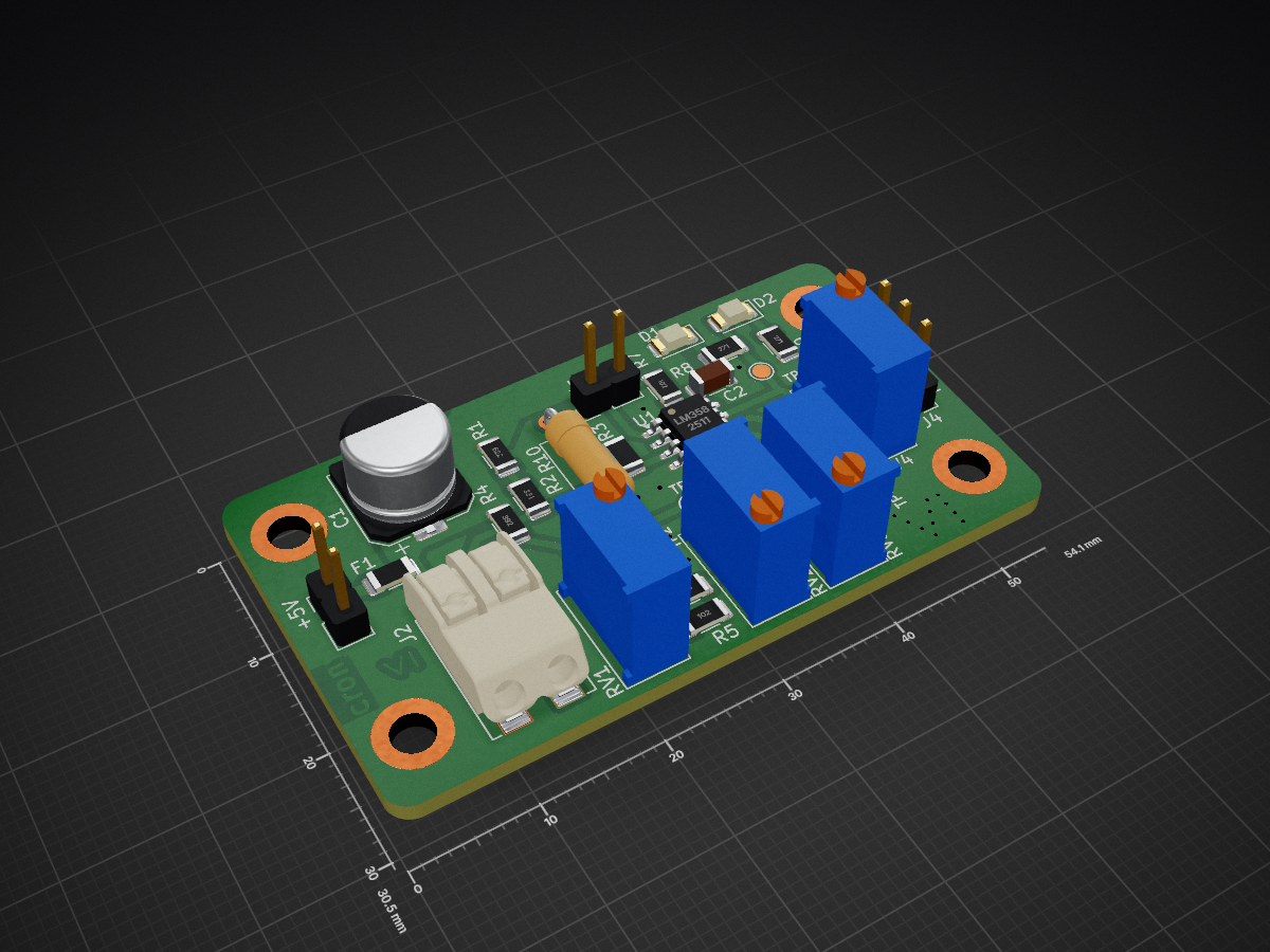
Tmp is an open-source printed circuit board by 0x007E, from the 0x007E/tmp repository on GitHub. It is a 2-layer board of 54.1 × 30.5 mm with 38 parts on 20 nets, routed with 65 tracks and 25 vias.
It is built around the LM358. Its parts include 11 resistors, 4 connectors, 2 capacitors, 2 diodes and 1 IC.


TMP - Temperature Warning (Temperaturwarnung)The TMP is a board with an LM358 or any other 2-channel operational amplifier. The board itself is driven with a voltage of 5V. It converts the temperature (0° - 100°) from an KTY81/210 to a voltage. This voltage can be coupled onboard with a Schmitt-Trigger to change the status of the connected LEDs (green, red).
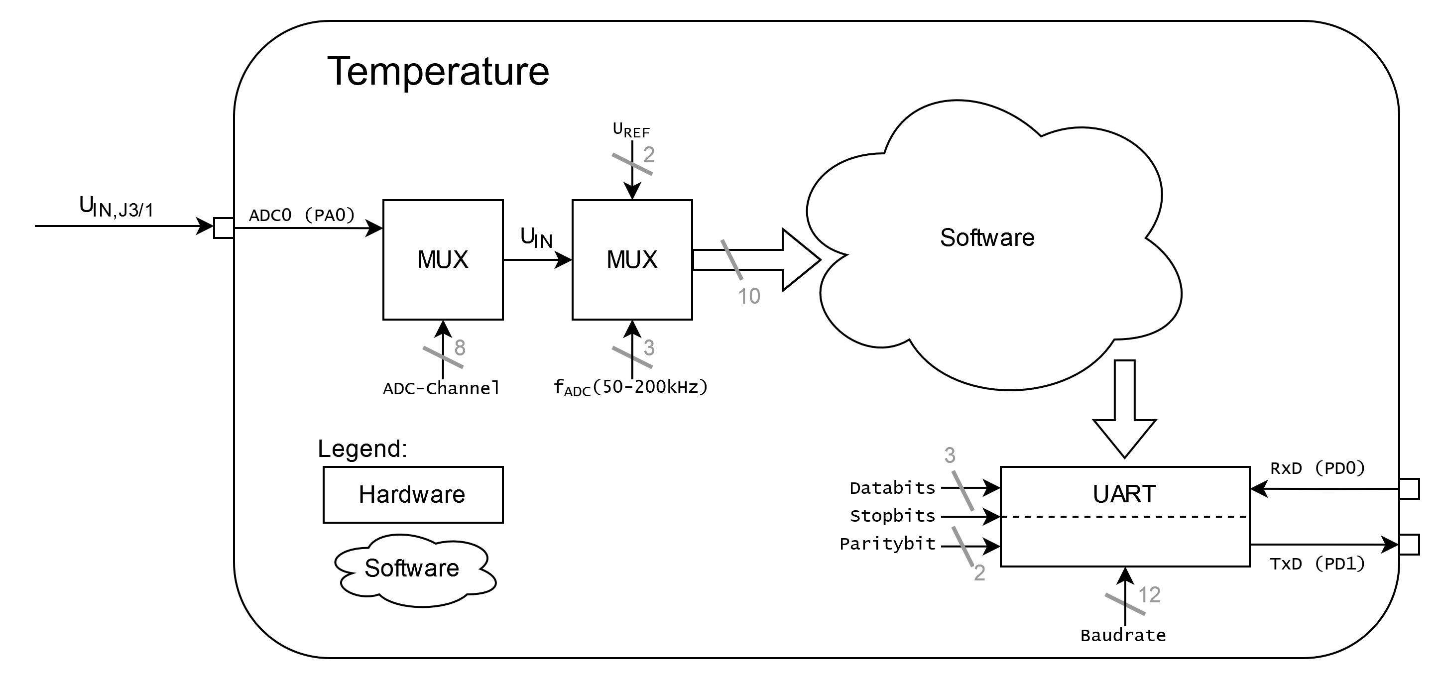
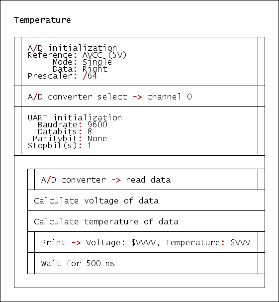
Optional the converted temperature can be digitalized through an A/D converter and sent to a terminal through UART. A demo how this can be done is attached and can be tested with an ATmega16A.
| Experience | Level |
|---|---|
| Soldering | |
| Software |
| Type | File | Description |
|---|---|---|
| Simulation | asc | LTSpice Simulation |
| Lochmaster | lm4 | Stripe grid circuit board |
| Schematic | pdf / cadlab | Schematic files |
| Board | pdf / cadlab | Board file |
| Drill | Drill file | |
| BoM | xlsx / html | Bill of Material as Excel/interactive HTML |
| PCB | zip / tar | KiCAD/Gerber/BoM/Drill files |
| Firmware | zip / tar | Demo Firmware for ATmega16 |
The pcb is created with KiCAD. All files are built with github actions so that they are ready for a production environment.
The circuit board is populated on one side. The best way for soldering the SMD components is within a vapor phase soldering system and for the THT components with a standard system.


To configure the TMP some reference voltages needs to be modified. The reference of TP2 has to be around ~1V and is adjusted through RV1. On J2 the KTY81/210 should be connected. To setup the amplification a mutimeter with temperature measurement function is needed. The voltage on TP3 can be calculated through the following equation:
$U_{TP3}=\frac{2.5}{100}*𝜗+1$
Calculate $U_{TP3}$ with the current temperature and setup the voltage on TP3 to the calculated value with RV2. The Equation is Designed for the following parameters:
| $U_{TP3}/[V]$ | Temperature $𝜗/[°C]$ |
|---|---|
| 1 | 0 |
| 3.5 | 100 |
On Jumper J3/1 the generated voltage from the captured temperature can be measured. To connect the temperature measurement to the warning system jumper J3 has to be shorten.
With RV3 the limit to generate a state change of the leds can be set to a value between 2° to 98°. With RV4 the hysteresis of the Schmitt-Trigger can be adjusted.
The demo firmware (ATmega16A) of the TMP can be used to digitalize the voltage with an A/D converter and transmit the data over uart to a terminal.
| Type | Link | Description |
|---|---|---|
| LM358 | Dual operational amplifier | |
| KTY81 | Temperature sensor 2 k0hm | |
| ATmega16A | Microchip ATmega16A Datasheet |
R. GAECHTER
| Qty | Value | Footprint | References |
|---|---|---|---|
| 5 | TestPoint_Probe | TestPoint:TestPoint_Pad_D1.5mm | TP1, TP2, TP3, TP4, TP5 |
| 4 | MountingHole_Pad | MountingHole:MountingHole_3.2mm_M3_DIN965_Pad | H1, H2, H3, H4 |
| 2 | 1k | Resistor_SMD:R_1206_3216Metric | R5, R7 |
| 2 | 250k | Potentiometer_THT:Potentiometer_Bourns_3296W_Vertical | RV2, RV4 |
| 2 | 270 | Resistor_SMD:R_1206_3216Metric | R8, R9 |
| 2 | Conn_01x02_Pin | Connector_PinHeader_2.54mm:PinHeader_1x02_P2.54mm_Vertical | J1, J3 |
| 1 | 0 | Resistor_SMD:R_1206_3216Metric | R11 |
| 1 | 0 | Resistor_THT:R_Axial_DIN0309_L9.0mm_D3.2mm_P12.70mm_Horizontal | R10 |
| 1 | 100m | Fuse:Fuse_1206_3216Metric | F1 |
| 1 | 100n | Capacitor_SMD:C_1206_3216Metric | C2 |
| 1 | 100u | Capacitor_SMD:CP_Elec_8x6.5 | C1 |
| 1 | 10k | Potentiometer_THT:Potentiometer_Bourns_3296W_Vertical | RV3 |
| 1 | 200 | Potentiometer_THT:Potentiometer_Bourns_3296W_Vertical | RV1 |
| 1 | 330 | Resistor_SMD:R_1206_3216Metric | R2 |
| 1 | 33k | Resistor_SMD:R_1206_3216Metric | R6 |
| 1 | 3k9 | Resistor_SMD:R_1206_3216Metric | R4 |
| 1 | 6k2 | Resistor_SMD:R_1206_3216Metric | R1 |
| 1 | BIN | Symbol:WEEE-Logo_4.2x6mm_SilkScreen | FID2 |
| 1 | Conn_01x02_Pin | Connector_Wago_SMD:WAGO_2060-402_998-404 | J2 |
| 1 | Conn_01x03_Socket | Connector_PinHeader_2.54mm:PinHeader_1x03_P2.54mm_Vertical | J4 |
| 1 | ESD | Symbol:ESD-Logo_6.6x6mm_SilkScreen | FID1 |
| 1 | Green | LED_SMD:LED_1206_3216Metric | D1 |
| 1 | LM358 | Package_SO:SOIC-8_3.9x4.9mm_P1.27mm | U1 |
| 1 | OH | Symbol:OSHW-Logo_5.7x6mm_SilkScreen | FID3 |
| 1 | QR | Images:QR_0x007e | FID4 |
| 1 | Red | LED_SMD:LED_1206_3216Metric | D2 |
| 1 | opt. | Resistor_SMD:R_1206_3216Metric | R3 |
It measures 54.1 × 30.5 mm and has 2 copper layers, 1.6 mm thick.
38 parts, built around the LM358. The full list of its parts is on this page, with links to each part's symbol and footprint where PCBKit's library has them.
From the 0x007E/tmp repository on GitHub, at the commit this page was made from: the board is pcb/TMP.kicad_pcb and its schematic pcb/TMP.kicad_sch. PCBKit opens the board in the browser, with nothing to install.
Its repository states no licence, so its author keeps all rights: ask 0x007E before reusing the design.
peterheinrich/InternetOverSpaghetti
Transmitting IP packages over a pair of spaghetti thus demonstrating how media independent IP really is.

zmaker/arduino_cookbook
gli sketch del nuovo progetto Arduino Cookbook e dei video di YouTube

profdc9/RFBitBanger
A QRP digital transceiver created from readily available parts for off-the-grid maintenance


tvlad1234/pillScopePlus
Oscilloscope based around the STM32F401 Black Pill and a color LCD screen


starlightk7/OpenSFC
OSHW Reproduction Parts related to the Super Famicom / Super Nintendo game console
