


4 layers70 × 72 mm

The board is powered over USB-C, regulates 5 V down to 3.3 V with a synchronous buck converter, and carries an 8-button input matrix (D-pad + A/B + Mode/Select) plus a dedicated reboot button, an external QSPI flash…
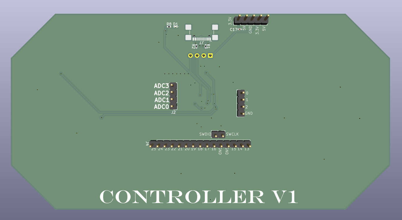
Rp2040 is an open-source printed circuit board by 0susi0, from the 0susi0/RP2040-Embedded-Controller repository on GitHub, published under the MIT licence. It is a 2-layer board of 145 × 75 mm with 48 parts on 62 nets, routed with 659 tracks and 48 vias.
It is built around the RP2040 and ABM8-272-T3. Its parts include 18 capacitors, 8 resistors, 7 connectors, 2 ICs and 1 diode. It belongs with the RP2040 boards of this library.
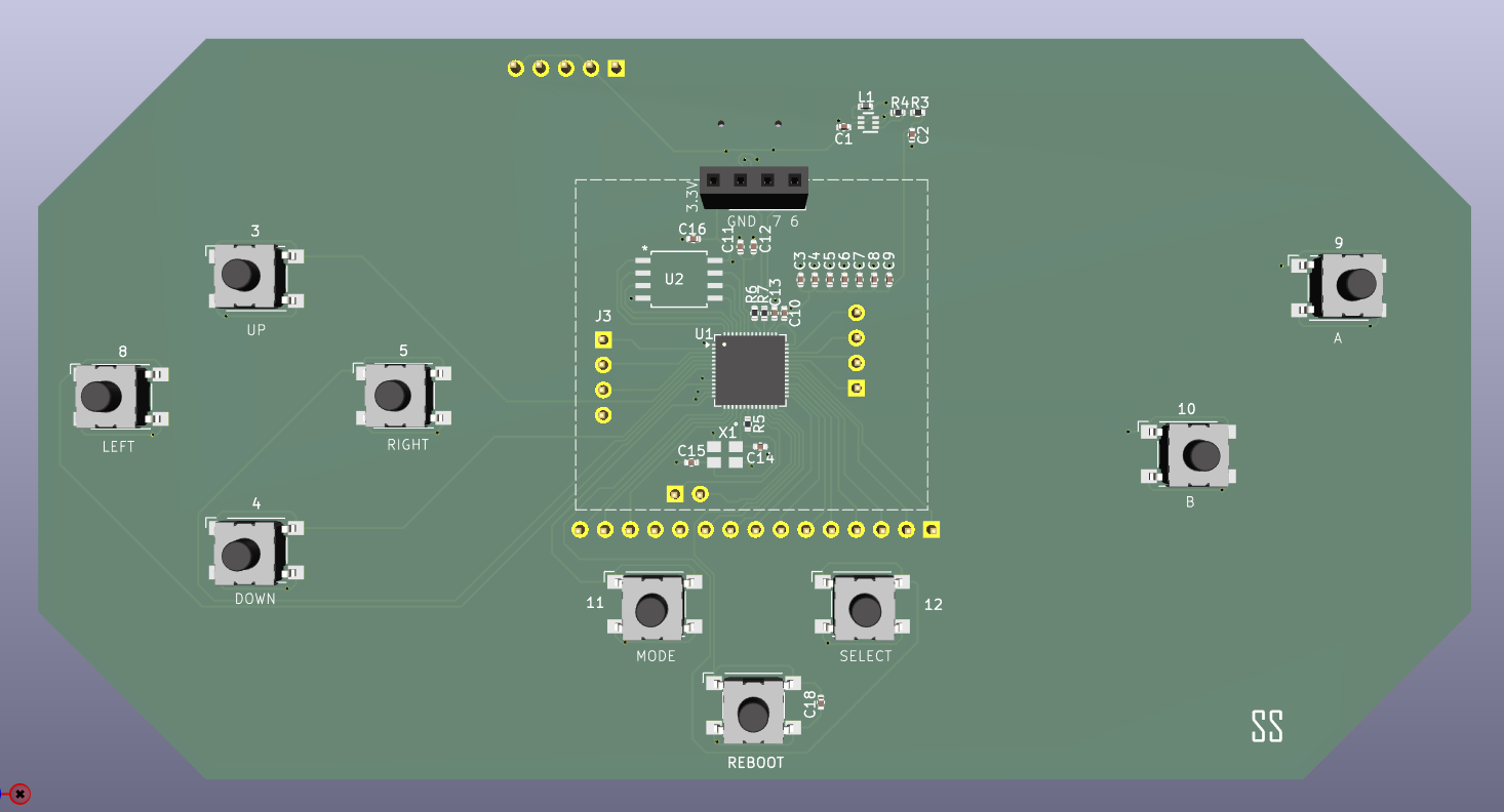




Controller V1 is a custom handheld game-controller board built around the Raspberry Pi RP2040 microcontroller. It was designed from scratch in KiCad, covering schematic capture, power design, and full PCB layout.
The board is powered over USB-C, regulates 5 V down to 3.3 V with a synchronous buck converter, and carries an 8-button input matrix (D-pad + A/B + Mode/Select) plus a dedicated reboot button, an external QSPI flash chip for program storage, an I²C header for a monochrome OLED, an SWD debug port, and a 4-channel ADC breakout — making it a solid base for handheld gaming and general embedded projects.
| Component | Description |
|---|---|
| MCU | Raspberry Pi RP2040 |
| Input Voltage | USB Type-C (5 V) |
| Regulator | TLV62569ADRLR buck converter |
| Output Voltage | 3.3 V |
| Flash Memory | Winbond W25Q128JVSIQ (QSPI) |
| Crystal | ABM8-272-T3, 12 MHz |
| Display Interface | I²C (SDA / SCK) header for monochrome OLED |
| Inputs | 8x tactile buttons + 1x reboot button |
| Analog | 4-channel ADC header |
| Debug | SWD (SWCLK / SWDIO) |
| PCB | 2 layers |
| CAD Software | KiCad 10 |
USB-C (5V)
   │
   ▼
TLV62569 Buck Converter (3.3V)
   │
   ▼
RP2040 MCU
   │
   ├── External QSPI Flash (W25Q128JVSIQ)
   ├── 12 MHz Crystal Oscillator
   ├── SWD Debug Header (SWCLK / SWDIO)
   ├── OLED Display Header (I²C: SDA / SCK)
   ├── 8x GPIO Buttons (UP/DOWN/LEFT/RIGHT/A/B/MODE/SELECT)
   ├── Reboot Button
   ├── 4-Channel ADC Header (ADC0-ADC3)
   ├── Full GPIO Breakout Header
   └── Status LED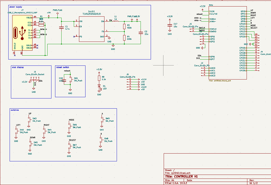
The power stage accepts 5 V from a USB-C receptacle and steps it down to 3.3 V using a TLV62569ADRLR buck converter, with input/output filter capacitors and feedback resistors sized for the 3.3 V rail. This sheet also contains the reboot switch, status LED, the OLED I²C header, the ADC breakout, the full GPIO pin header, and the full button matrix (D-pad, A/B, Mode/Select).
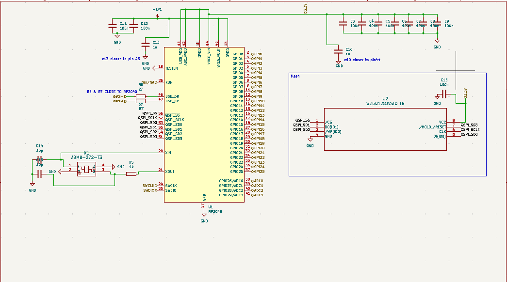
The MCU sheet includes:
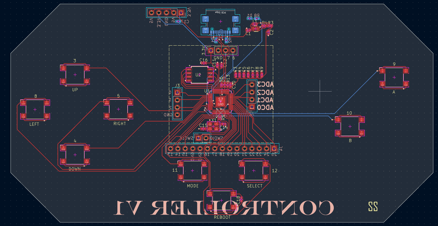
RP2040-Embedded-Controller
│
├── Hardware
│   ├── KiCad          # Schematic + PCB project files (.kicad_sch, .kicad_pcb, .kicad_pro)
│   ├── PDFs           # Exported schematic/PCB PDFs
│   ├── Gerbers        # Manufacturing files (Gerbers + drill files)
│   └── BOM            # Bill of materials
│
├── Images
│   ├── PCB_Top_3D.png
│   ├── PCB_Bottom.png
│   ├── PCB_Layout.png
│   ├── Schematic_Power.png
│   └── Schematic_MCU.png
│
├── README.md
└── LICENSEThis project provided hands-on experience in:
Susindharan S
Electrical & Electronics Engineering
Interested in:
This project is licensed under the MIT License.
| Qty | Value | Footprint | References |
|---|---|---|---|
| 11 | 100n | Capacitor_SMD:C_0402_1005Metric | C3, C4, C5, C6, C7, C8, C9, C11, C12, C16, C18 |
| 9 | SW_Push | Button_Switch_SMD:SW_SPST_Omron_B3FS-101xP | 3, 4, 5, 8, 9, 10, 11, 12, REBOOT |
| 2 | 15p | Capacitor_SMD:C_0402_1005Metric | C14, C15 |
| 2 | 1u | Capacitor_SMD:C_0402_1005Metric | C10, C13 |
| 2 | 27 | Resistor_SMD:R_0402_1005Metric | R6, R7 |
| 2 | 5.1k | Resistor_SMD:R_0402_1005Metric | R1, R2 |
| 2 | Conn_01x04_Pin | Connector_PinHeader_2.54mm:PinHeader_1x04_P2.54mm_Vertical | J2, J3 |
| 1 | 100k | Resistor_SMD:R_0402_1005Metric | R4 |
| 1 | 10u | Capacitor_SMD:C_0402_1005Metric | C17 |
| 1 | 1k | Resistor_SMD:R_0402_1005Metric | R5 |
| 1 | 1u | Inductor_SMD:L_0402_1005Metric | L1 |
| 1 | 2.2k | Resistor_SMD:R_0402_1005Metric | R8 |
| 1 | 22u | Capacitor_SMD:C_0402_1005Metric | C2 |
| 1 | 4.7u | Capacitor_SMD:C_0402_1005Metric | C1 |
| 1 | 453k | Resistor_SMD:R_0402_1005Metric | R3 |
| 1 | ABM8-272-T3 | crystal:ABM8-272-T3_ABR | X1 |
| 1 | Conn_01x02_Pin | Connector_PinHeader_2.54mm:PinHeader_1x02_P2.54mm_Vertical | J5 |
| 1 | Conn_01x04_Socket | Connector_PinSocket_2.54mm:PinSocket_1x04_P2.54mm_Vertical | J1 |
| 1 | Conn_01x05_Pin | Connector_PinHeader_2.54mm:PinHeader_1x05_P2.54mm_Vertical | J6 |
| 1 | Conn_01x15_Pin | Connector_PinHeader_2.54mm:PinHeader_1x15_P2.54mm_Vertical | J4 |
| 1 | LED | LED_SMD:LED_0402_1005Metric | D1 |
| 1 | RP2040 | Package_DFN_QFN:QFN-56-1EP_7x7mm_P0.4mm_EP3.2x3.2mm | U1 |
| 1 | TLV62569ADRLR | buck:DRL0006A | buck1 |
| 1 | USB_C_Receptacle_USB2.0_16P | Connector_USB:USB_C_Receptacle_GCT_USB4110 | J7 |
| 1 | W25Q128JVSIQ TR | flash:SOIC_208MIL_WIN | U2 |
It measures 145 × 75 mm and has 2 copper layers, 1.6 mm thick.
48 parts, built around the RP2040 and ABM8-272-T3. The full list of its parts is on this page, with links to each part's symbol and footprint where PCBKit's library has them.
From the 0susi0/RP2040-Embedded-Controller repository on GitHub, at the commit this page was made from: the board is Hardware/KiCad/rp2040.kicad_pcb and its schematic Hardware/KiCad/rp2040.kicad_sch. PCBKit opens the board in the browser, with nothing to install.
Its repository publishes it under the MIT licence: you may reuse it on that licence's terms (keep the author's notice, and for a copyleft licence share your changes alike).

jackw01/scanlight
A better light source for scanning color negative film

HandHeldLegend/GC-Ultimate
The 3D shell, buttons, and other associated models are licensed under a Creative Commons Attribution 4.0 International License .


ikajdan/katia
A split keyboard with 6 by 3 column staggered keys and 3 thumb keys, based on the Crkbrd design

alvarop/swd2usbc
Have you ever wanted to debug your device over USB-C? Sometimes there's not enough room for a JTAG/SWD connector, or even Tag-Connect pads!
